INSTALLATION AND OPERATION INSTRUCTIONS
1-16
HC SERIES BOILERS HC 13-50, HC 23-84, HC 29-106, HC 20-125, HC 33-160
CONDENSATE REMOVAL
IBC’s specied vent conguration promotes the safe drainage of moisture from
the boiler and exhaust venting without owing liquids back through the heat
exchanger.
Reliable system operation requires (1) proper design and installation of exhaust
venting to allow condensate to run back to the drain/trap; (2) acid neutralization
as appropriate. To achieve these:
1. Allow for a 1/4" per foot slope back to the vent connection, with appropriate
hangers to maintain that gradient.
2. Ensure the supplied trap is correctly installed and lled with water.
3. When required, add (and maintain in good condition) a neutralization tank.
1.5.1 Condensate Trap
A condensate trap must be installed on the drain connection at the base of the
boiler as shown in Figure 18.
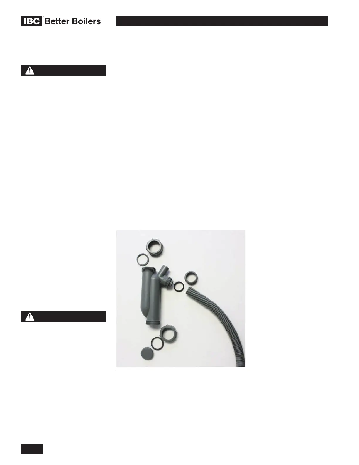
1.5.2 Condensate Trap Assembly - Installation
1. Undo Drain Spout Compression Nut, remove Drain Hose from Trap Drain
Outlet. Remove Upper Compression Nut and Washer and slide over Boiler
Drain Outlet (A). Insert one Trap Hook barb into the back mounting hole.
2. Fill Trap with water, and slide Trap Body over Boiler Drain Outlet (A). Swing
Trap Hook (B) around the Drain Outlet connection threads. Insert remaining
Trap Hook barb into the front hole. Pull the trap slightly downward to seat it
against the hook and tighten Upper Compression nut.
3. Attach Drain Hose and tighten Drain Spout Compression Nut.
1.5
WARNING
The Trap Hook must be
installed as instructed and all
trap ttings must be tightened
as instructed to prevent
leakage of ue gasses.
Failure to comply may result
in severe personal injury or
death.
WARNING
Fill trap with water before
boiler is rst red to prevent
exhaust fumes from entering
room. Never operate the
boiler unless the trap is lled
with water.
Failure to comply will result
in severe personal injury or
death.
Figure 17: Condensate Trap, disassembled
 Loading...


