1-17
INSTALLATION
HC SERIES BOILERS HC 13-50, HC 23-84, HC 29-106, HC 20-125, HC 33-160
1.5.3 Condensate Trap Assembly - cleaning procedure
1. Turn off the power to the boiler and allow it to cool down.
2. Remove the trap from the boiler (reverse the installation procedure above).
3. Remove the Trap Cleanout Assembly, from the Trap Body and clean and
ush the debris out.
4. Re-assemble trap components, re-ll trap, and replace on boiler as described
in the installation instructions above.
1.5.4 Further installation details
• Condensate drain must be piped to within 1" of a drain or be connected to a
condensate pump.
• Drainage line must slope down to the drain at a pitch of 1/4" per foot so
condensate runs towards the drain.
• Condensate traps should be checked every 2 months, and cleaned and
relled as necessary.
NOTE
It is the responsibility of
the installing and/or service
Contractor to advise and
instruct the end User in how
to perform the Trap cleaning
procedure, and to advise
that the Trap be checked at
least every two months and
cleaned as required.
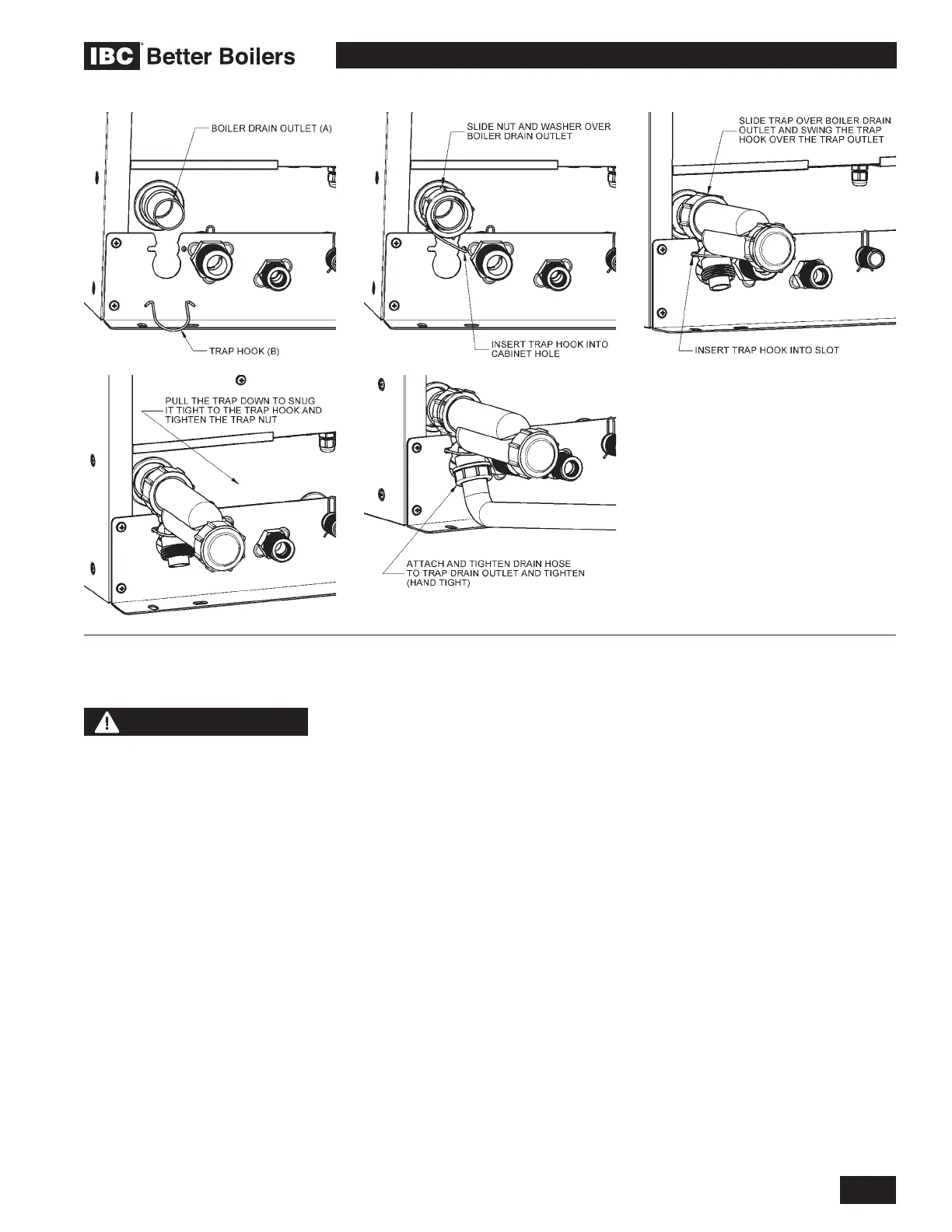
Figure 18: Condensate trap installation
 Loading...


