INSTALLATION AND OPERATION INSTRUCTIONS
1-6
VFC 15-150, VFC 45-225 MODULATING GAS BOILERS
1.4.3 Vent Travel
CPVC or PPs (Rigid Single Wall) piping is the standard venting option; with
this, the VFC 15-150 boiler, for example, can be sited up to 50 equivalent feet
from the vent termination using 2” or up to 120’ using 3”. The actual vent travel
allowance is reduced for ttings in accordance with Table 4. – e.g. for an VFC
15-150 using 6 x 90º CPVC elbows, the maximum lineal measure of pipe allowed
using 3” pipe is 72 feet (120’ – (6 x 8’ = 48) = 72’).
For 3” exible PPs, up to 60 actual lineal feet are allowed in a nominally vertical
orientation (>45°). The equivalent length of 3” ex PPs shall be computed using
a multiple of 3:1, eg. 45’ x 3 = 135’ equivalent (for the VFC 45-225). With 45’ of 3”
ex, up to 105’ equivalent of 3” rigid PPs would still be allowed. 2” exible PPs is
not allowed.
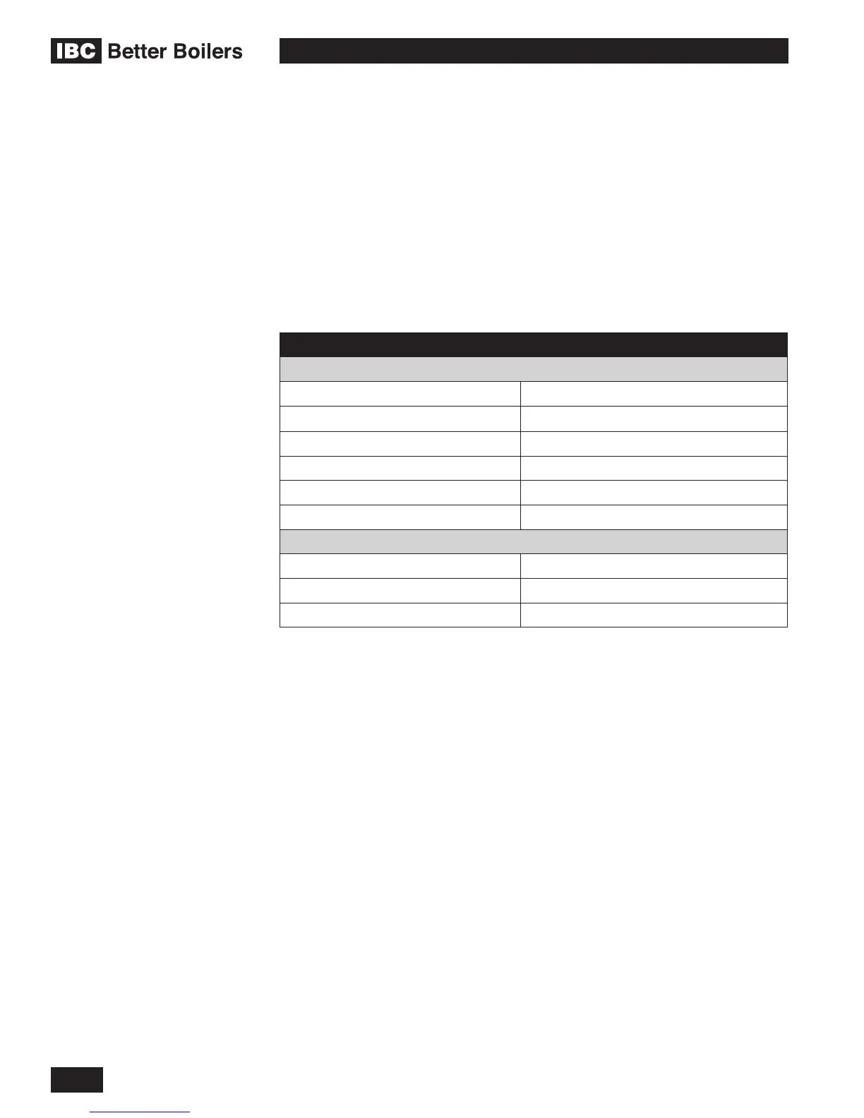
EXHAUST PIPE SIZE MAXIMUM EQUIVALENT LENGTH
Sched.40; Rigid PPs
2" (15-150 only) 50' (each side)
3" (15-150) 120'
3" (45-225) 240'
90° vent elbow allow 8' equivalent
45° elbow allow 3’ equivalent
PPs 87-90° elbow allow 8’ equivalent
Flexible PPs
2” Flexible N/A
3” Flexible (VFC 15-150) 60’ (max) actual lineal x 1.5 = equivalent
3” Flexible (VFC 45-225) 60’ (max) actual lineal x 3 = equivalent
Table 4: Maximum exhaust venting length
Note: Unused intake travel cannot be added to the exhaust. Unequal intake
and exhaust piping is allowed (see Section 1.4.8).
Exhaust venting must slope down towards the boiler with a pitch of at least 1/4”
per foot (PPs vent: follow PPs manufacturer requirements) so condensate runs
back towards the trap. Support should be provided for intake and vent piping,
particularly so for horizontal runs (follow local code). Insulate exhaust piping
where it passes through unheated spaces or underground, with appropriate pipe
insulation to prevent freezing of condensates.
Certain installations of the VFC 15-150 model can employ the 2” vent options. We
caution installers when using horizontal runs of 2” pipe. Reason: air friction from the
fast moving exhaust during long burner runs at high-re in a 2” pipe can overcome
gravity on 1/4” / foot vent slope – leaving a pool of condensate at the next upturned
elbow. Pooling can impair the achievement of full high-re rating plate performance
.
If the site requires a horizontal exit immediately below the boiler – bush out to
3" pipe in the downward vertical run immediately below the 2" threaded adaptor,
and elbow to horizontal before splicing in a eld sourced 3" reducing tee for
mounting of the condensate trap; this will slow the exhaust velocity sufciently for
good drainage and reduce “spitting” at the vent termination. In this case, the 3" x
3/4" reducing tee would replace the 2" tee and 2" x 3/4" bushing supplied with the
VFC 15-150 boiler.

 Loading...


