3
©Copyright LOTRONIC 2016 DJLIGHT65
Specifications
Power supply ....................................................................................... AC 220-240, 50/60Hz
Consumption ................................................................................................................. 60W
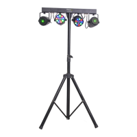
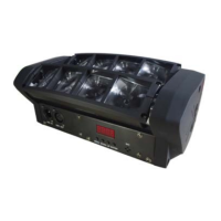
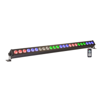
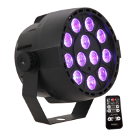
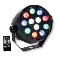
PAR cans ............................................................................................ 12 x 1W RGBW LED x 2
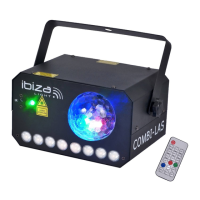
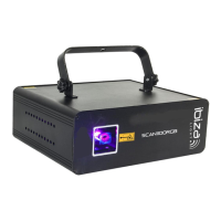
Laser ........................................................................................... Red: 100mW; green 30mW
Laser class ............................................................................................................................ 3
Height ................................................................................................................. 1.80m max.
Weight........................................................................................................................... 6.7kg
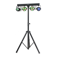
Installation of the units
Before positioning the light stand, ensure the stability of the installation site. Drive the screw into the screw hole
on the stand. Make sure that the units can’t fall from the stand. The manufacturer cannot be held responsible
for damages due to bad installation of the units.
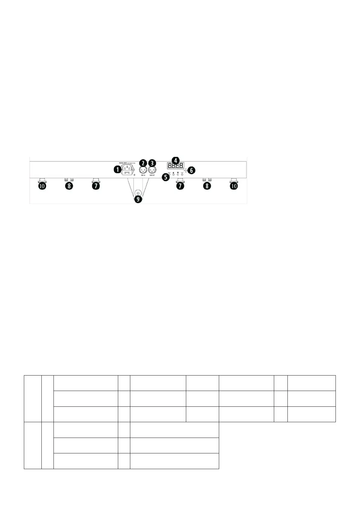
Connections
1. Power supply input: Attach the IEC mains cable here. Built-in fuse
2. DMX input: 3-pin XLR connector for DMX512 signal input
3. DMX output: 3-pin XLR connector for DMX512 signal output
4. LED display: Display of the functions and menu buttons to control the operating mode
5. MENU buttons: See below for operation
6. Mic: Built-in microphone for sound controlled operation
7. PAR can mounts: Attach the PAR cans to the controller bar at the 2 points shown
8. PAR & Laser connections: Connect the PAR & laser at the 2 points shown
9. Light stand socket: Tighten the screw to secure the controller bar to the light stand
10. Laser mounts: Fasten the Laser units to the controller bar at the 2 points shown.
MENU BUTTONS
You can set the operating mode of the unit via the 4 function buttons on the controller bar. Press the MENU
button to display the different functions (see table below for a detailed description of the functions). Use the UP
and DOWN arrow buttons to make your selection. Once you have chosen your desired function, press the ENTER
button to confirm the change.
Button Specifications:
Auto
↔
↔
AP01-AP13: PAR light
effect
AutF: Laser auto
operation
↔
S01-S32: Laser effect
speed
AutN: Light set auto
operation
↔
Sou
↔
SouP: PAR sound
activated
↔
SP01-SP13: PAR light effect
SouF: Laser Sound
activated
↔
SF01-SF07: Laser light effect
SouN: Light set sound
activated
↔
SN01-SN10: Light set sound
activated