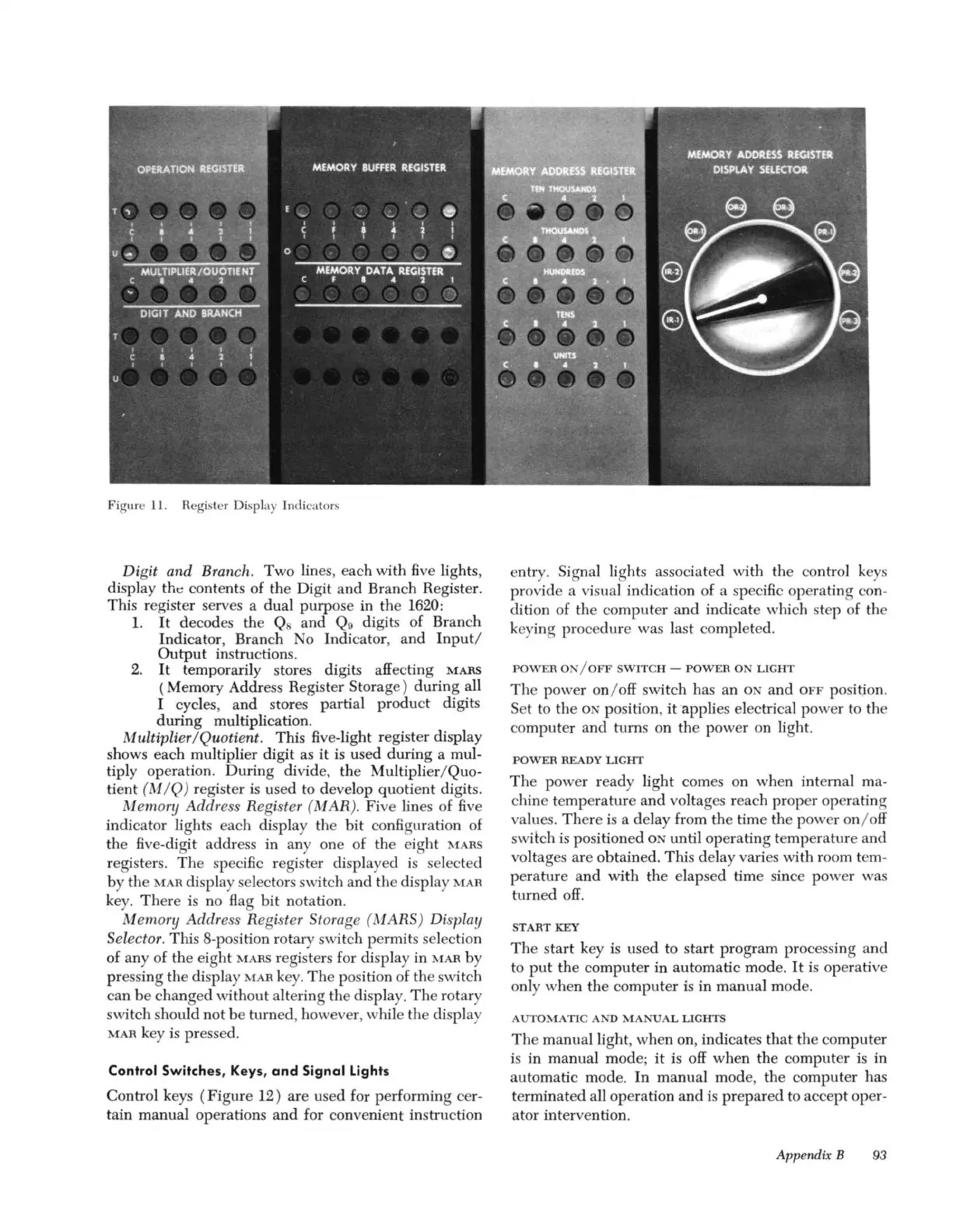
Figure
11
. Register Display Indicators
Digit
and
Branch. Two lines, each with five lights,
display
tht: contents of the Digit and Branch Register.
This register serves a dual purpose
in
the 1620:
1.
It
decodes the Q and
Q9
digits of Branch
Indicator, Branch
No
Indicator, and
Input/
Output
instructions.
2.
It
temporarily stores digits affecting
MARS
( Memory Address Register Storage) during all
I cycles, and stores partial product digits
during multiplication.
Multiplier/Quotient. This five-light register display
shows each multiplier digit as it is used during a mul-
tiply operation. During divide. the Multiplier/Quo-
tient
(M
/Q) register
is
used to develop quotient digits.
Memory Address Register
(MA
R). Five lines of five
indicator lights each display the bit configuration of
the five-digit address in
anyone
of the eight
MARS
registers.
The
specific register displayed
is
selected
by the
MAR
display selectors switch and the display
MAR
key.
There
is
no
Bag
bit
notation.
Memory Address Register Storage ( MARS) Display
Selector.
This 8-po ition rotary switch permits selection
of any of the eight
MARS
registers for display in
MAR
by
pressing the display
MAR
key.
The
position of the switch
can
be
changed without altering the display.
The
rotary
switch should
not
be
turned, however, while the display
MAR
key is pressed.
Control
Switches,
Keys,
and
Si
gnal
Lights
Control keys
(Figure
12) are used for performing cer-
tain manual operations and for convenient instruction
entry.
Signal lights associated with the conh'ol keys
provide a visual indication of a specific operating con-
dition of the computer and indicate which st p of the
keying procedure was last completed.
POWER
0 /
OFF
SWITCH
-
POWER
ON
LIGHT
The
power on/
off
switch has an
ON
and
OFF
position.
Set
to
the
0 position, it"applies electrical power to the
computer and turns on the power on light.
POWER
READY
LIGHT
The
power ready light comes on when internal ma-
chine temperature
and
voltages reach proper operating
values. There
is
a delay from the time the power on/
off
switch
is
positioned 0 until operating temperature and
voltages are obtained. This delay varies with room tem-
perature and with the elapsed time since power was
turned
off.
START
KEY
The
start key
is
used to start program processing and
to
put
the computer in automatic mode.
It
is
operative
only when the computer
is
in manual mode.
AUTO
<lATIC
AND
MANUAL
LIGHTS
The
manual light, when on, indicates that the computer
is
in manual mode;
it
is
off
when the computer
is
in
automatic mode. In manual mode, the computer has
terminated all operation and
is
prepared
to accept oper-
ator intervention.
Appendix B 93