A B
1 1
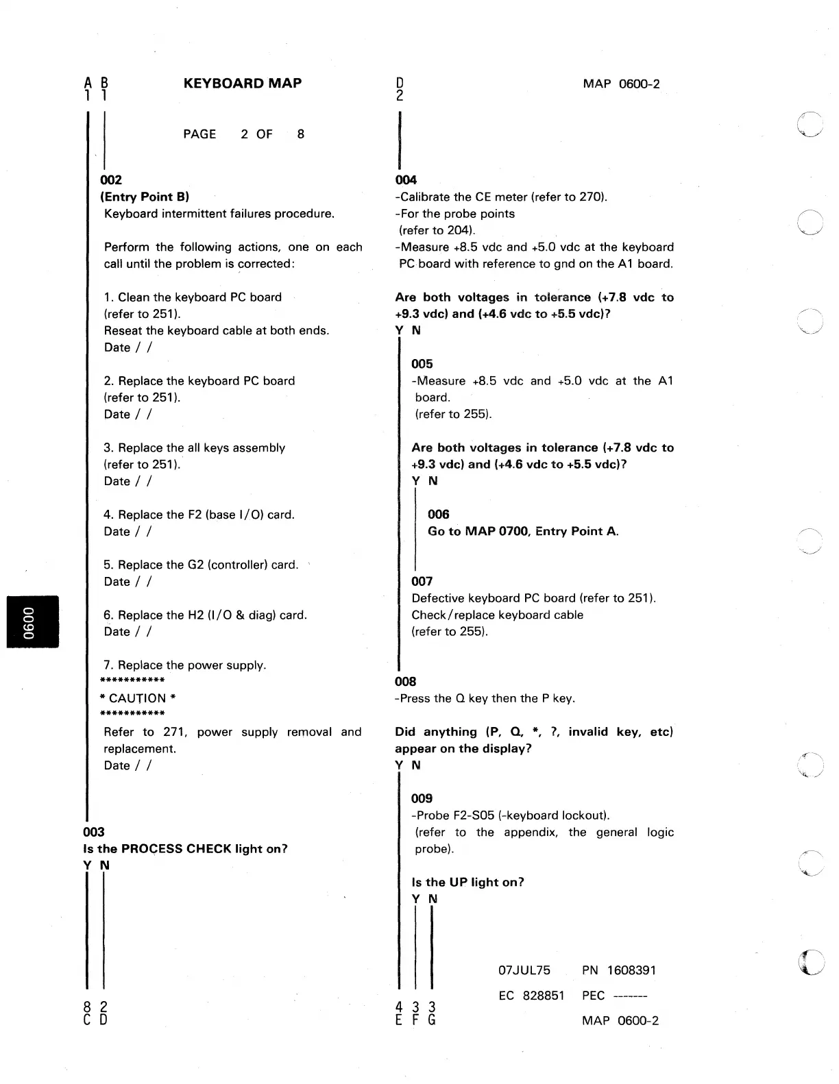
002
KEYBOARD
MAP
PAGE
2
OF
8
(Entry
Point
B)
Keyboard intermittent failures procedure.
Perform the following actions, one on each
call until the problem is
~orrected:
1 . Clean the keyboard
PC
board
(refer
to
251).
Reseat the keyboard cable at both ends.
Date / /
2.
Replace the keyboard
PC
board
(refer
to
251).
Date / /
3.
Replace the all keys assembly
(refer
to
251).
Date / /
4. Replace the
F2
(base
I/O)
card.
Date / /
5.
Replace the G2 (controller) card.
Date / /
6.
Replace the H2
(I/O
& diag) card.
Date / /
7.
Replace the power supply.
***********
* CAUTION *
***********
Refer
to
271, power supply removal and
replacement.
Date / /
003
Is
the
PRO<;:ESS
CHECK
light
on?
Y N
8 2
C 0
o
2
MAP
0600-2
004
-Calibrate the
CE
meter (refer
to
270).
-For the probe points
(refer
to
204).
-Measure +8.5 vdc and +5.0 vdc at the keyboard
PC
board with reference
to
gnd
on
the A 1 board.
Are
both
voltages
in
tole~anee
(+7.8
vde
to
+9.3 vde)
and
(+4.6
vde
to
+5.5 vde)?
Y N
005
-Measure +8.5 vdc and +5.0 vdc at the A 1
board.
(refer
to
255).
Are
both
voltages
in
tolerance
(+7.8
vde
to
+9.3
vdel
and
(+4.6
vde
to
+5.5 vde)?
Y N
006
Go
to
MAP
0700,
Entry
Point
A.
007
Defective keyboard
PC
board (refer
to
251).
Check/replace keyboard cable
(refer
to
255).
008
-Press the
Q key then the P key.
Did
anything
(P,
Q,
*,
?,
invalid
key,
etc)
appear
on
the
display?
Y N
009
-Probe F2-S05 (-keyboard lockout).
(refer to the appendix, the general logic
probe).
Is
the
UP
light
on?
Y N
07JUL75
PN
1608391
433
E F G
EC
828851
PEC
-------
MAP 0600-2
c
c
o

 Loading...


