D E
1 1
POWER
MAP
PAGE 2
OF
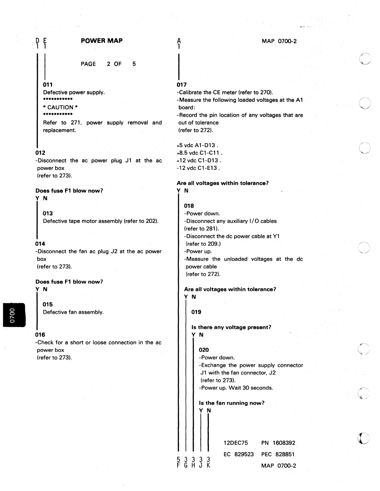
011
Defective power
slAPply.
•••••••••••
*
CAUTION·
•••••••••••
Refer
to
271, power supply removal
~nd
replacement.
012
-Disconnect the
ac
power plug J 1 at the ac
power box
(refer
to
273).
Does
fuse
F1
blow
now?
Y N
013
Defective tape motor assembly (refer
to
202).
014
-Disconnect the fan ac plug
J2
at the
ae
power
box
(refer
to
273).
Does
fuse
F1
blow
now?
Y N
015
Defective fan assembly.
016
-Check
for
a short or loose .connection
in
the
ac
power box
(refer
to
273).
A
1
017
MAP
07()()...2
-Calibrate the
CE
meter (refer
to
270).
....
,
"I.
-Measure the following loaded voltages at the
A1
board:
-Record the pin location
of
any voltages that are
out
of
tolerance
(refer
to
272).
+5
vdc A1-D13 .
+8.5 vdc C1-C11 .
+ 12 vdc
C1-D13.
-12 vdc C1-E13 .
Are
all
voltages
within
tolefance?
Y N
018
-Power down.
-Disconnect any auxiliary
I/O
cables
(refer
to
281).
-Disconnect the dc power cable at
Y1
(refer
to
209.)
-Power up.
-Measure the unloaded voltages at the
dc
power cable
(refer
to
272).
Are
all
voltages
within
tolerance?
Y N
019
Is
there
any
voltage
present?
Y N
020
-Power down.
-Exchange the power supply connector
J1
with the fan connector,
J2
(refer
to
273).
-Power up.
Wait
30
seconds.
Is
the
fan
running
now?
Y N
5 3 3
3.3
F G H J K
12DEC75
PN
1608392.
EC
829523
PEC
828851
MAP 0700-2
c

 Loading...


