EasyManuals Logo

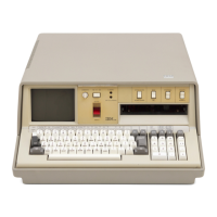
IBM 5100 Maintenance Analysis Procedures

IBM 5100
136 pages
To Next Page IconTo Next Page
To Previous Page IconTo Previous Page
Page #115 background imageLoading...
Page #115 background image
(
(
(
(
(
(
H J K
222
021
POWER
MAP
PAGE 3
OF
5
Check/
replace the cables
in
the ac
power
box.
(refer
to
273).
022
Are
the
voltages
present
now?
Y N
023
Defective powei' supply.
***********
* CAUTION *
***********
Refer
to
271,
power
supply removal and
replacement.
024
A cable
was
unseated
or
had
an
open
connection. Inspect
for
loose connections.
025
Defective
power
supply.
***********
* CAUTION *
***********
Refer
to
271,
power
supply removal and
replacement.
G
2
MAP
0700-3
026
(Entry
Point
B)
-Power down.
-Connect the
dc
cable back into socket
Y1
.
-Disconnect
a"
the cables
to
the A 1 board except
the
dc
power
cable.
-Power up.
-Measure one
of
the out
of
tolerance voltages
recorded above
for
the next several steps.
Does
fuse
F1
blow
or
does
power
drop?
Y N
027
Is
the
measured
voltage
out
of
tolerance
now?
Y N
028
-Connect the Z4 (keyboard) cable.
Is
the
measured
voltage
out
of
tolerance
now?
Y N
029
-Connect the Z2 (tape) cable.
Is
the
measured
voltage
out
of
tolerance
now?
Y N
030
-Connect
the
Z3 (display and control
panel) cable.
Is
the
measured
voltage
out
of
tolerance
now?
Y N
12DEC75
PN
1608392
EC
829523
PEC
828851
5 5 5
444
L M N P Q R
MAP
0700-3

Other manuals for IBM 5100

Questions and Answers:

Question and Answer IconNeed help?

Do you have a question about the IBM 5100 and is the answer not in the manual?

IBM 5100 Specifications

General IconGeneral
Release Year1975
RAM16 KB - 64 KB
Storage204 KB tape drive
Display5-inch CRT
Operating SystemAPL/BASIC
ProcessorIBM PALM (1.9 MHz)

Related product manuals