Choosing a Mode of Operation
VNET Switch Mode — Single VNET
Protocol
Port1
Port2
Port3
Port4
Port1
Port2
Port3
Port4
SystemBus
10BaseT
HUB5
10BaseT
HUB7
10BaseT
HUB8
10BaseT
HUB6
10BaseT
HUB4
10BaseT
HUB2
Net1
Net1
Net1
Net1
Net1
Net1
Net1
Net1
LANDriver
Adapter1 Adapter 2
Port1
Port2
Port3
Port4
Port1
Port2
Port3
Port4
LANDriver
VirtualNetwork Layer
10BaseT
HUB3
VNET
Switch 1
10BaseT
HUB1
.
.
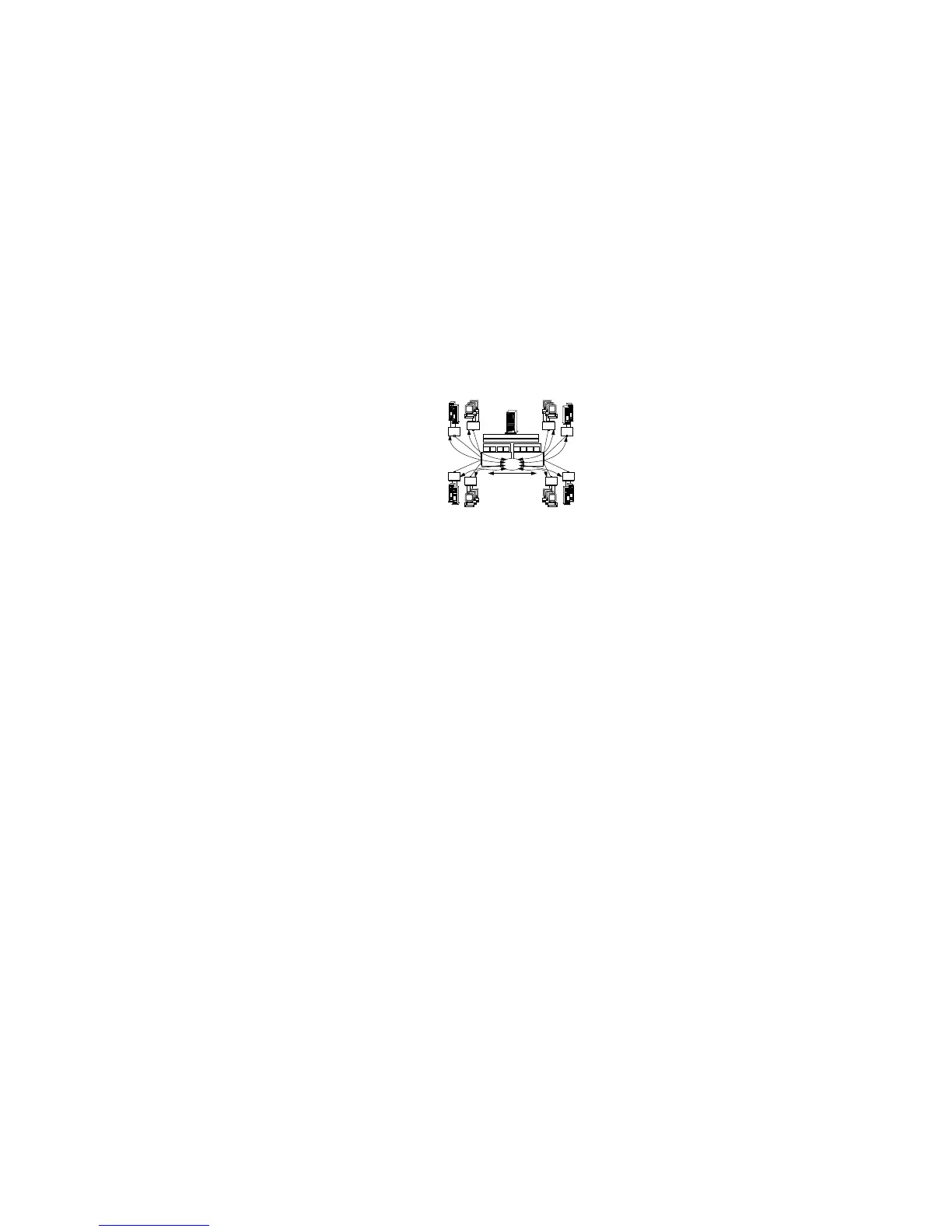
The illustration shows:
A subnet network (Net 1) composed of eight physical segments.
Two PeerMaster adapters configured as one large VNET.
When the PeerMaster adapters are configured as one large
VNET, they act as a high-performance network adapter as well
as an integrated subsystem (based upon BusBIOS) that provide
media-rate Ethernet switching between network devices across
all LAN segments.
A VNET registering all eight active segments with the protocol
as a single subnetwork.
Curved arrows indicating the flow of cross-segment traffic in the
VNET.
Devices can roam (physically detached and reattached) among
segments within a VNET, without loss of active sessions to the
server or to peer devices throughout the VNET.
The PeerMaster subsystem and the VNET driver dynamically
detect the relocation of the device and remap traffic for that
device in real time.
All cross-segment traffic is forwarded by the PeerMaster subsystem;
therefore, server responsiveness is not compromised due to heavy
cross-segment traffic.
The PeerMaster adapter performs two types of packet switching,
port-to-port and peer-to-peer.
142 PC Server 520 User's Handbook for PCI/EISA