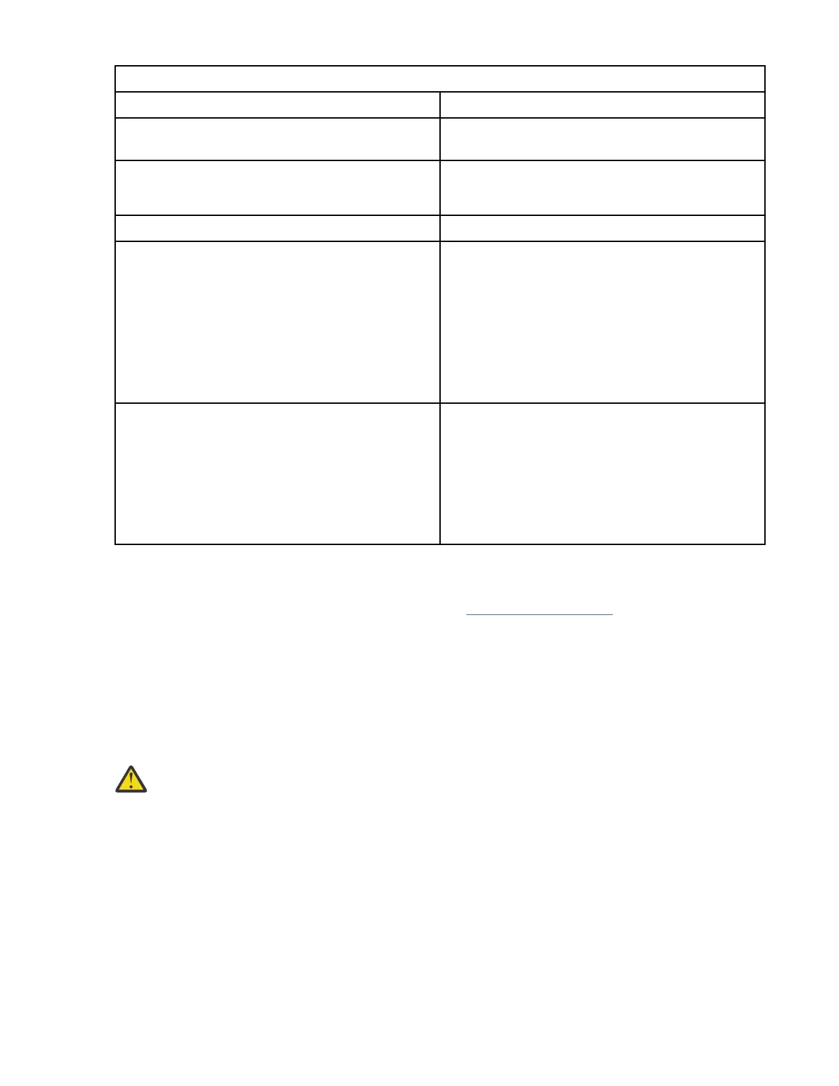
Table 4. Heat exchanger water specications
Water Specications
Source User-supplied, compliant with specications in this
document
Pressure Normal operation: <137.93 kPa (20 psi)
Maximum: 455 kPa (66 psi)
Volume Approximately 9 liters (2.4 gallons)
Temperature Above dew point
18°C ±1°C (64.4°F ±1.8°F) for ASHRAE Class 1
Environment
22°C ±1°C (71.6°F ±1.8°F) for ASHRAE Class 2
Environment
Note: See “Heat exchanger performance” for more
information.
Required water flow rate (as measured at the
supply entrance to the heat exchanger)
The flow rate of the water in the system must be in
the range of 23 - 57 liters (6 - 15 gallons) per
minute.
Pressure drop versus flow rate for heat exchangers
(including quick-connect couplings) is dened as
approximately 34 kPa ( 5 psi) at 57 liters (15
gallons) per minute.
Heat exchanger performance
Select the correct water inlet temperature and water flow rate to achieve the necessary heat removal.
Expected performance of the heat exchanger is shown in Figure 102 on page 145 for a typical inlet air
temperature of 27°C (80.6°F), with a fully populated rack, near uniform power dissipation, and a 30 kW
heat load.
A heat removal of 100% indicates that an amount of heat equivalent to that generated by the devices has
been removed by the heat exchanger and the average air temperature leaving the heat exchanger is
identical to that entering the rack (27°C [80.6°F] in this example). Heat removal in excess of 100%
indicates that the heat exchanger not only removed all of the heat generated by the devices but further
cooled the air so that the average air temperature leaving the rack is actually lower than that entering the
rack.
Attention:
To help maintain optimum performance of the rear door heat exchanger and provide proper
cooling for all rack components, you must always take the following precautions:
1. Install ller panels over all unoccupied bays.
2. Route signal cables at the rear of the rack so that they enter or exit the cabinet through the top
and bottom air baffles.
3. Bundle signal cables together in a rectangle so that the upper and lower air-baffle sliders are
closed as far as possible. Do not bundle signal cables together in a circular formation.
The following illustration shows the typical performance of the heat exchanger, 30kW heat load.
144
Power Systems: Racks and rack features
 Loading...