Note: If the hole locations selected at the rear of the rack are not accessible, riggers will be required
to install the mounting hardware in the non-accessible hole locations. You must lift the rack to install
the hardware.
22. If you are installing a 7014-T42 rack with the X brace feature, go to step “27” on page 18.
Otherwise, continue with step “23” on page 18.
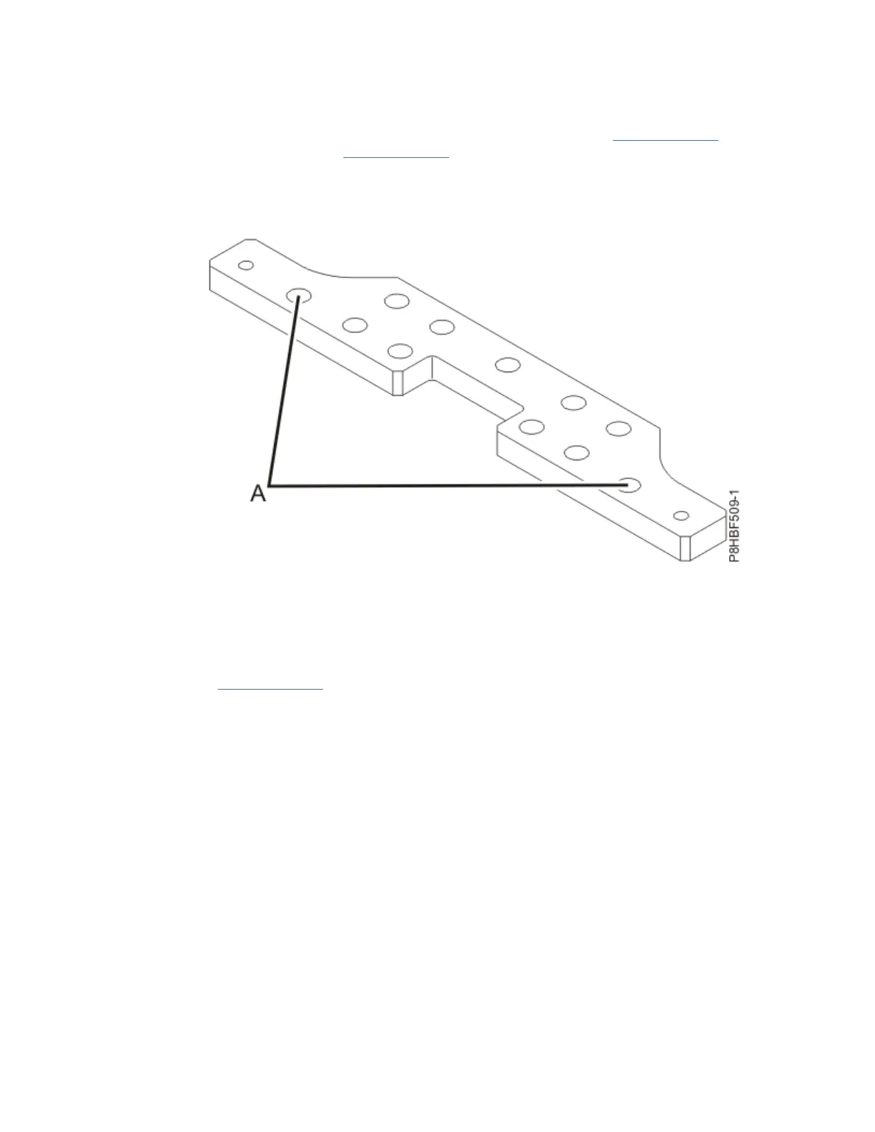
23. For each rack-mounting plate, select at least two suitable hole locations (A). Select the hole locations
as close to the threaded hole areas as possible. Drill pass-through holes at the selected locations into
the raised floor panels. The pass-through holes allow the mounting hardware to be inserted into the
rack-mounting plate and pass through the raised floor panel to the concrete floor.
Figure 13. Bolt-down plate hole locations for rack with the triangular brace
24. Transfer the locations of the anchor bolt holes (exclude the clearance holes drilled for the rack-
mounting bolts) from the raised-floor panel to the concrete floor directly beneath, and mark the hole
locations on the concrete floor.
25. Drill holes in the concrete floor to secure the anchor bolts.
26. Go to step “30” on page 19.
27. For each rack-mounting plate, select at least four suitable hole locations (A). Select the hole
locations as close to the threaded hole areas as possible. Drill pass-through holes at the selected
locations into the raised floor panels. The pass-through holes allow the mounting hardware to be
inserted into the rack-mounting plate and pass through the raised floor panel to the concrete floor.
18
Power Systems: Racks and rack features
 Loading...