Installing Memory-Module Kits
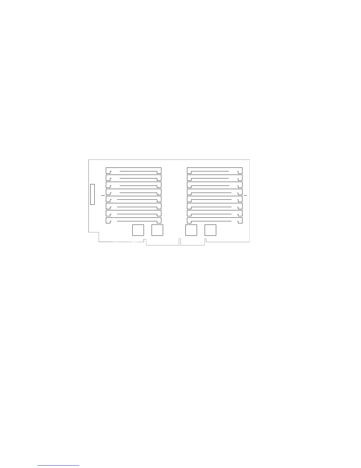
The following illustration shows the memory-module connectors for
all models.
Bank 2
Bank 1
Bank 2
Bank 1
J16
J14
J12
J10
J8
J6
J4
J2
J15
J13
J11
J9
J7
J5
J3
J1
16 Attention:
a. Reduce the risk of electrostatic discharge (ESD) damage
to the memory modules and memory board by following
the instructions in Notice Number 10.
b. To avoid breaking the retaining clips or damaging the
sockets, handle the clips gently.
116 PC Server 704 User's Handbook
 Loading...
