• Use a 50.8 mm (2 in.) or larger supply pipe to provide the correct flow to three 19 mm (0.75 in.)
supply hoses, with a 100 kW coolant distribution unit (CDU).
• Use a 63.5 mm (2.50 in.) or larger supply pipe to provide the correct flow to four 19 mm (0.75 in.)
supply hoses, with a 120 kW CDU.
• Use an 88.9 mm (3.50 in.) or larger supply pipe to provide the correct flow to nine 19 mm (0.75 in.)
supply hoses, with a 300 kW CDU.
To stop the flow of water in individual legs of multiple circuit loops, install shutoff valves for each
supply and return line. This provides a way to service or replace an individual heat exchanger without
affecting the operation of other heat exchangers in the loop.
To ensure that water specications are being met and that the optimum heat removal is taking place,
use temperature and flow metering (monitoring) in secondary loops.
Anchor or restrain all manifolds and pipes to provide the required support and to avoid movement
when quick-connect couplings are being attached to the manifolds.
Flexible hoses and connections to manifolds and heat exchangers:
Pipe and hose congurations can vary. You can determine the best conguration for your installation
by analyzing the needs of your facilities, or a site preparation representative can provide this analysis.
Flexible hoses for the cold-water supply and warm water return are provided with the delivery of the
rear door heat exchanger (allowing needed movement for opening and closing the rack rear door). The
customer needs to supply a 2.54 cm (1 in.) female national pipe thread (NPT) tting for each supply
and return hose connection to the facility. The IBM supplied hoses contain the quick connect ttings
to mate to the ttings on the rear door heat exchanger.
Use solid piping or tubing that has a minimum inner diameter of 19 mm (0.75 in.) and the fewest
possible joints between a manifold and a heat exchanger in each secondary loop.
Related information
Installing the rear door heat exchanger
Planning for the 7965-S42 rack
Rack specications provide detailed information for your rack, including dimensions, electrical, power,
temperature, environment, and service clearances.
Model 7965-S42 rack specications
Hardware specications provide detailed information for your rack, including dimensions, electrical,
power, temperature, environment, and service clearances.
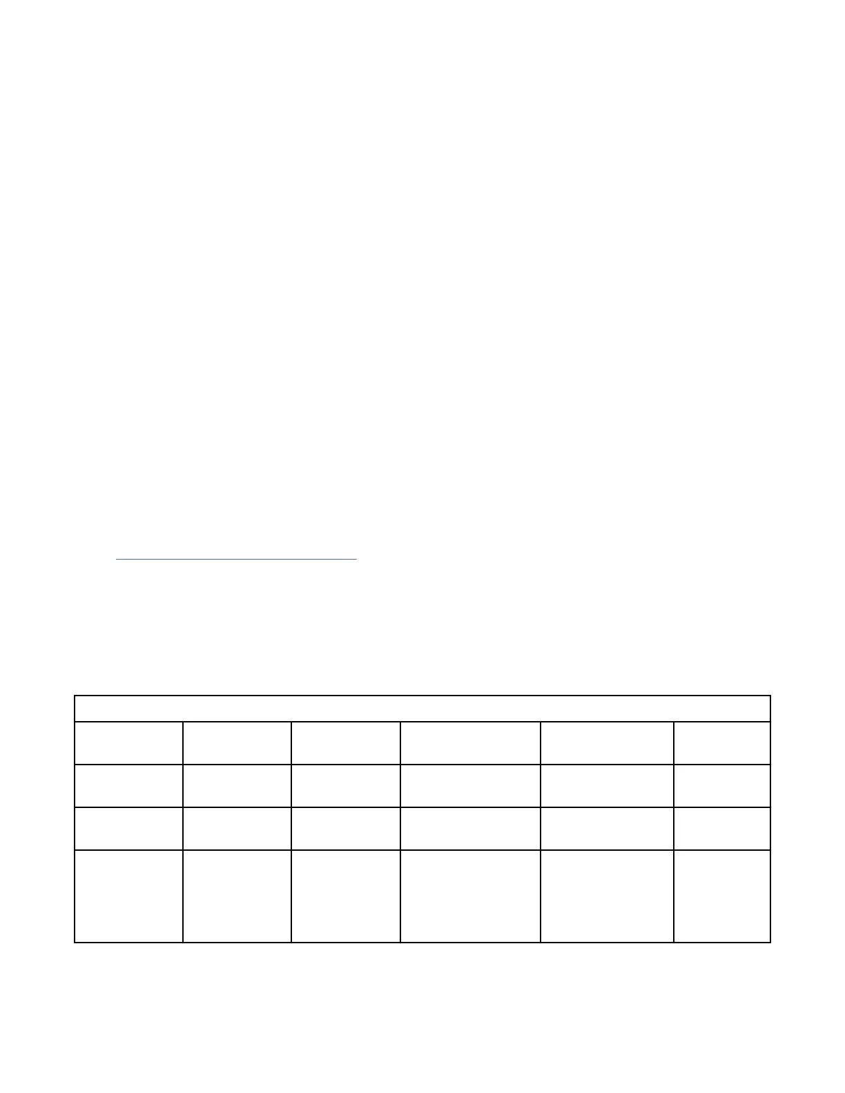
Table 54. Dimensions for rack
Width Depth Height Weight (Empty)
EIA unit
capacity
Rack only
600 mm (23.6
in.)
1070 mm (42.1
in.)
2020 mm (79.5 in.) 166 kg (365 lb) 42 EIA units
Rack with two
standard doors
600 mm (23.6
in.)
1132 mm (44.6
in.)
2020 mm (79.5 in.) 177 kg (391 lb) 42 EIA units
Rack with rear
door heat
exchanger (dry)
and standard
doors
600 mm (23.6
in.)
1231 mm (48.5
in.)
2020 mm (79.5 in.) 210 kg (463 lb) 42 EIA units
Site and hardware planning 51
 Loading...