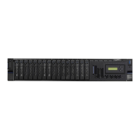
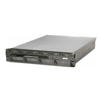
Figure 1. Rear view of a rack-mounted 9040-MR9 system with PCIe slots location codes
Table 3 on page 2 lists the adapter slot locations and details for the 9040-MR9 systems.
Table 3. Slot locations and descriptions for the 9040-MR9 system
Location code Description SCM / PHB Slot capabilities Slot availability
OpenCAPI PCIe3 cable
adapter
Dynamic direct
memory access
(DMA) window
Enlarged capacity
assign order
1
2 processors 3 processors 4 processors
P1-C2 PCIe4 x16 3/3 No Yes Yes 8 No No Yes
P1-C3 PCIe4 x16 3/0 Yes Yes Yes 4 No No Yes
P1-C4 PCIe4 x16 2/3 No Yes Yes 7 No Yes Yes
P1-C5 PCIe4 x16 2/0 Yes Yes Yes 3 No Yes Yes
P1-C6 PCIe3 x8 (Base
Ethernet adapter use
only
1/2 No No Yes 9 Yes Yes Yes
P1-C7 PCIe4 x16 1/3 No Yes Yes 6 N/A N/A N/A
P1-C8 PCIe4 x16 1/0 Yes Yes Yes 2 Yes Yes Yes
P1-C9 PCIe4 x 8 (SAS
controller slot for
controlling internal
disk bays)
1/1 No No Yes 11 Yes Yes Yes
P1-C10 PCIe4 x16 0/3 Yes Yes Yes 5 Yes Yes Yes
P1-C11 PCIe4 x16 0/0 No Yes Yes 1 Yes Yes Yes
P1-C12 PCIe4 x8 (SAS
controller slot for
controlling internal
disk bays)
0/1 No No Yes 10 Yes Yes Yes
1
Assigned PCIe slot order when the I/O Adapter Enlarged Capacity option is enabled. For example, if the option was enabled with a value of 5, ve slots are enabled with the I/O enlarged capacity.
Note: Enabling the I/O Adapter Enlarged Capacity option will only affect Linux
®
partitions. If your system does not have Linux partitions, the I/O Adapter Enlarged Capacity setting should be disabled.
Note the following:
• The I/O cassettes that are used in the 9040-MR9 system can hold half length, full height and half length, half height PCIe adapters.
• All PCIe slots support the single root I/O virtualization (SR-IOV) function.
2Power Systems: Adapter placement for the 9040-MR9

 Loading...


