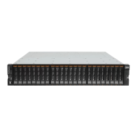
Storwize V7000 Gen3 Ethernet networking adapters
Each node canister also supports optional 2-port 25 Gbps internet Wide-area RDMA Protocol (iWARP) or RDMA over Converged Ethernet
(RoCE) Ethernet networking adapters. Install the 25 Gbps Ethernet adapters according to the following guidelines. Record the port
connections for the Ethernet adapters in the following table.
• Fibre Channel adapters must be installed before Ethernet adapters, beginning with slot 1 and then slot 2.
• iWARP and RoCE Ethernet adapters cannot be mixed within a node canister.
• Ethernet adapters are installed beginning with the rst available slot.
• By default, a 4-port 16 Gbps SAS adapter is installed in slot 3. However, only ports 1 and 3 are used to establish a SAS connection.
Control Enclosure S/N:
Node Canister Component
Ethernet Adapter Slot 1 Ethernet Adapter Slot 2
Adapter slot 3
Port 5 Port 6 Port 7 Port 8
1 (upper) Switch N/A
Port
Speed: 25 or 10 Gbps
2 (lower) Switch N/A
Port
Speed: 25 or 10 Gbps
Storwize V7000 Gen3 Fibre Channel connections
Each node canister supports one or two 4-port 32 Gbps Fibre Channel (FC) adapters or 4-port 16 Gbps FC adapters. Install the FC adapters
according to the following guidelines. Then, record the FC port connections in the following table.
• Install the rst FC adapter in adapter slot 1.
• Install the second FC adapter, if applicable, in adapter slot 2.
• Adapter slot 3 cannot be used for FC adapters.
Control Enclosure S/N:
Node
Canister
Component
FC Adapter slot 1 FC Adapter slot 2
Adapter
Slot 3
Port 1 Port 2 Port 3 Port 4 Port 5 Port 6 Port 7 Port 8
1 (upper) Switch or host N/A
Port
Speed: 32, 16, or 8 Gbps
2 (lower) Switch or host N/A
Port
Speed: 32, 16, or 8 Gbps
Management and service address worksheet
Use the following table to record the management address and service addresses for each control enclosure . The primary system address
is bound to Ethernet port 1. The secondary system address, if specied, is bound to Ethernet port 2. Both IPv4 and IPv6 addresses can be
used. Specify the type of installation and the serial number (S/N) of the control enclosure.
• If you are installing a new system installation, designate new, unused IP addresses.
• If you are adding an I/O group (control enclosure) to an existing system, use the management address of the existing system.
Control Enclosure S/N:
Are you adding this control enclosure to an existing system? ❐ Yes ❐ No
Address Type IP Address Network Mask Default Gateway
Primary system address (required)
Secondary system address (optional)
Node canister 1 service address (required)
11

 Loading...