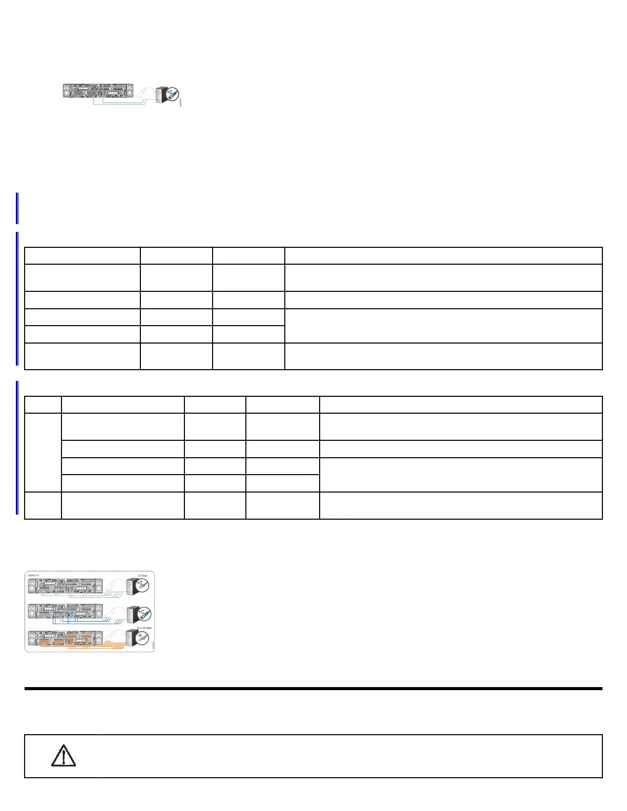
Connecting Ethernet cables
1. Connect Ethernet port 1 of each node canister to the IP network that will provide connection to the system management interfaces.
Ethernet port 1 can be used for iSCSI connectivity to the system by hosts on the network. If the
system has more than one control enclosure, ensure port 1 of every node canister is connected to the
same network to provide access if the conguration node fails.
2. Optionally, connect Ethernet port 2 of each node canister in the system to a second IP network that will provide redundant connection to
the system management interfaces. Port 2 can also be used for iSCSI connectivity to the system by hosts on the network. If the system
contains more than one control enclosure, ensure that port 2 of every node canister is connected to the same network to provide access
if the conguration node fails.
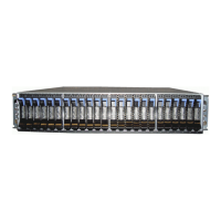
Connecting other networking cables
Each control enclosure has PCIe slots that support optional networking adapters. However, the location requirements for the networking
adapters differ between the FlashSystem 7200 and Storwize V7000 Gen3 control enclosures. Use the information that you entered in
Network cable worksheets on page 9 to establish the proper connections.
On FlashSystem 7200 systems, the networking adapters can be installed in any PCIe slot.
Type
Adapter Ports Total Adapters Purpose
16 Gbps Fibre Channel (FC) 4 0-3 Supports NVMe over Fabrics (NVME-oF). Required for adding control enclosures, up
to a maximum of four per system.
32 Gbps FC 4 0-3 Supports simultaneous SCSI and NVMeFC connections on the same port.
25 Gbps Ethernet (iWARP) 2 0-3 Supports iSCSI or iSER host attachment.
25 Gbps Ethernet (RoCE) 2 0-3
12 Gbps SAS adapter 4 (2 active) 1 Required to connect to expansion enclosures. If ordered, this adapter is
preinstalled in PCIe slot 3.
On Storwize V7000 Gen3 systems, the networking adapters must be installed according to the following guidelines.
Slot
Type Adapter Ports Total Adapters Purpose
1 or 2 16 Gbps Fibre Channel (FC) 4 0-2 Supports NVME-oF. Required for adding control enclosures, up to a
maximum of four per system.
32 Gbps FC 4 0-2 Supports simultaneous SCSI and NVMeFC connections on the same port.
25 Gbps Ethernet (iWARP) 2 0-2 Supports iSCSI or iSER host attachment.
25 Gbps Ethernet (RoCE) 2 0-2
3 12 Gbps SAS adapter 4 (2 active) 1 Required to connect to expansion enclosures. This adapter is preinstalled
in PCIe slot 3.
1. Ensure that the networking adapters are installed in the appropriate PCIe slot.
2. Connect the required number of FC or Ethernet cables to the ports on each node canister. Both node canisters must have the same
number of cables connected.
Powering on the system
After you install all hardware components, you must power on the system and check its status. Each control enclosure has two power
supply units (PSUs). To provide redundancy in a power failure, connect the power cords to separate power circuits.
Attention: Do not power on the system with any open drive bays or host interface adapter slots. Open bays or PCIe slots
disrupt the internal air flow, causing the drives to receive insufcient cooling. Filler panels must be installed in all empty
drive bays and PCIe slots.
6