EasyManua.ls Logo

IBM FlashSystem 7200 User Manual

IBM FlashSystem 7200
17 pages
To Next Page IconTo Next Page
Page #1 background imageLoading...
Page #1 background image
IBM FlashSystem 7200
IBM Storwize V7000 Gen3
NVMe Control Enclosure
Getting Started Guide IBM
Overview
This document describes the installation procedures for the following IBM FlashSystem
®
and Storwize
®
systems. It also contains
information to help you plan the system conguration. This information applies to the following machine type and model (MTM) numbers.
System
MTMs
IBM FlashSystem 7200 control enclosure 2076-824 and 2076-U7C
Storwize V7000 Gen3 NVMe control enclosure 2076-724 and 2076-U7B
Important: This document is intended to be used by persons who are experienced with installing these systems. Before you use this
information and the product it supports, read the following topics:
Installation worksheets on page 8
Safety and environmental notices on page 12
Notices on page 13
IBM Systems Environmental Notices and IBM Systems Safety Notices (provided on a DVD with your product order)
IBM Knowledge Center (https://ibm.biz/BdqxdY) contains more information about preparing the physical environment before the
installation; it also provides information about conguring, managing, and servicing the system after installation. The IBM Knowledge
Center is updated between product releases to provide the most current documentation.
Unpacking and verifying the contents
Before you start the installation process, ensure that the following items are available.
Philips screw driver
Box knife
Flat-blade screw driver (optional)
Three Ethernet cables
The control enclosure and the following related parts are included in one box. The enclosed inventory sheet lists the part numbers of the
items that were ordered. Items, such as drives and networking adapters, are preinstalled inside each node canister.
Control enclosure with the following components preinstalled:
Two node canisters with optional networking adapters, SFPs, and memory.
Each IBM FlashSystem 7200 node canister contains three networking adapter slots. The same number and type of adapters must be
installed in each node canister. The control enclosure can contain 0, 2, 4, or 6 networking adapters.
Each Storwize V7000 Gen3 node canister has three adapter slots. By default, slot 3 contains a 4-port 12 Gbps SAS networking
adapter. If ordered, the same number and type of networking adapters are installed in slots 1 and 2 of each node canister. The
control enclosure can contain 2, 4, or 6 networking adapters.
Two power supply units (PSUs).
A combination of 24 drives and drive blanks.
The number of drives and drive blanks varies, according to the number of drives that were specied in the product order. For
example, if 12 drives were ordered, the drives and 12 drive blanks are preinstalled in the control enclosure.
Rail kit, which includes the left and right rails, and 8 securing M5 screws and locating pins.
Cables, if they were ordered, for the type and number of networking adapters that are installed in each node canister.
Two power cables.
1
Question and Answer IconNeed help?

Do you have a question about the IBM FlashSystem 7200 and is the answer not in the manual?

IBM FlashSystem 7200 Specifications

General IconGeneral
Form Factor2U
CoolingRedundant, hot-swappable fans
Power SupplyDual, hot-swappable
Supported DrivesSSD
Host Interface16Gb/32Gb FC, 10Gb/25Gb iSCSI, 12Gb SAS
RAID LevelsRAID 0, 1, 5, 6, 10
Height8.7 cm
Width44.7 cm

Summary

Overview

System and MTMs

Lists system types and their corresponding machine type and model (MTM) numbers.

Important Information

Highlights key topics for users installing the system, including safety and environmental notices.

IBM Knowledge Center

Provides information on preparing the physical environment and system configuration.

Unpacking and Verifying Contents

Required Items for Installation

Lists essential tools and cables needed before starting the installation process.

Included System Components

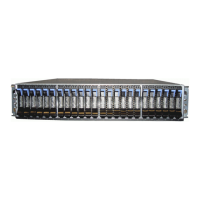
Details the parts included in the box, such as node canisters, power supplies, and drives.

Unpacking the Control Enclosure

Enclosure Unpacking Procedure

Provides detailed steps for safely removing the control enclosure from its shipping carton.

Serial Number Recording

Instructs users to record serial numbers for PSUs, node canisters, and the control enclosure itself.

Installing Rails and Enclosure into Rack

Support Rail Installation

Explains how to attach the side support rails to the rack cabinet flanges.

Enclosure Rack Mounting

Details how to mount the control enclosure into the rack using mounting screws.

Removing and Replacing Parts

Power Supply Unit (PSU) Removal/Installation

Provides instructions on how to remove and reinstall power supply units (PSUs) for weight reduction.

Node Canister Procedures

Node Canister Removal and Installation

Guides users through the process of removing and reinstalling node canisters from the control enclosure.

Drive Procedures

Drive Removal and Replacement

Details the procedure for removing and replacing a drive or an IBM FlashCore Module (FCM).

SAS Cable Connections

Connecting to Expansion Enclosures

Explains how to connect the control enclosure to SAS-attached expansion enclosures.

Networking Cable Connections

Onboard Ethernet Port Functions

Describes the function and speed of onboard Ethernet ports for system connectivity.

Ethernet Cable Connections

System Management Network Setup

Details connecting Ethernet port 1 for management and iSCSI connectivity.

Redundant Network Connectivity

Explains connecting Ethernet port 2 for redundant management and iSCSI connectivity.

PCIe Networking Adapters

Supported Adapter Types

Lists supported networking adapters for PCIe slots and their purposes.

Adapter Installation Guidelines

Provides guidelines for installing Fibre Channel and Ethernet adapters in PCIe slots.

System Power-On Procedures

Pre-Power-On Checks

Advises to check for open drive bays or PCIe slots before powering on the system.

System Power-On and Status Verification

Power Cable Management and Routing

Instructions for securing power cables to PSUs using retainers.

Status LED Indicator Interpretation

Explains how to check status LEDs on the control enclosure for operational status.

System Setup and Configuration

Initial System Setup via Technician Port

Guides on connecting to the technician port and initial system setup.

Service Assistant Tool Configuration

Details using the Service Assistant Tool and initialization GUI for IP settings.

Adding Enclosure to Existing System

Management GUI Enclosure Addition

Instructions to add a new enclosure to an existing system using the management GUI.

Browser and Worksheet Information

Supported Browser Requirements

Lists compatible browsers and required enabled features for the management GUI.

Drive Configuration Worksheet

Provides a worksheet to record drive information for each slot in the control enclosure.

Network Cable Worksheets

Ethernet Cable Standards Summary

Summarizes Ethernet cable types, standards, and connectors used.

Onboard Ethernet Port Configuration Table

Table for recording onboard Ethernet port properties for node canisters.

FlashSystem 7200 Ethernet Adapter Guidelines

Guidelines for installing iWARP or RoCE Ethernet adapters in FlashSystem 7200.

FlashSystem 7200 Fibre Channel (FC) Connections

FC Adapter Installation Guidelines

Details on installing Fibre Channel (FC) adapters in FlashSystem 7200.

FC Port Connection Data Recording

Table for recording FC port connections on each node canister.

Storwize V7000 Gen3 Ethernet Adapters

Ethernet Adapter Installation Guidelines

Guidelines for installing 25 Gbps Ethernet adapters in Storwize V7000 Gen3.

Storwize V7000 Gen3 Fibre Channel (FC) Connections

FC Adapter Installation Guidelines

Details on installing Fibre Channel (FC) adapters in Storwize V7000 Gen3.

Management and Service Address Worksheet

IP Address Configuration Recording

Worksheet for recording management and service IP addresses for control enclosures.

Safety and Environmental Notices

Telecommunication Environment Suitability

Notes on the product's intended use and limitations regarding public telecommunication networks.

Identifying Safety Notice Details

Instructions on how to find and understand safety notices using identification numbers.

Environmental and Compliance Information

Required Environmental Statements

Information on environmental notices for IBM Systems products.

Product Design and Certification Standards

Details compliance with IEC standards and relevant certifications.

System Accessibility Features

Major Accessibility Features Overview

Lists key accessibility features like screen reader support and keyboard navigation.

IBM Accessibility Commitment

Human Ability and Accessibility Center Reference

Reference to IBM's center for accessibility commitments.

Document Notices and Disclaimers

Material Availability and License Inquiries

Information on material availability, licensing, and patent inquiries.

Warranty and Legal Disclaimer Statements

Details on warranty, liability, and legal disclaimers for the publication.

Copyright and Trademark Information

Sample Program License Terms

Terms for using sample application programs provided in source language.

Limited Warranty Statement Location

Information on where to find the limited warranty statement.

Trademark and Homologation Details

IBM and Third-Party Trademarks

Lists IBM trademarks and mentions Microsoft and Windows.

Telecommunication Connection Certification

Notes on certification requirements for connecting to public telecommunication networks.

Electromagnetic Compatibility (EMC) Notices

Class A EMC Compliance and Monitor Cables

States compliance with Class A EMC standards and requirements for monitor cables.

European Community and Morocco EMC Notice

EU EMC Directive Conformity

Confirmation of conformity with EU directive for electromagnetic compatibility.

German EMC Notice

German Law and EU EMC Directive Compliance

Details Germany's compliance with the EU EMC directive and EN 55032 Class A.

Japanese JEITA Notice

Harmonic Current Suppression Requirements

Information on harmonic current suppression for devices.

Japanese VCCI Notice

Class A IT Device Residential Interference Warning

Warning about potential electromagnetic interference in residential environments.

Regional Notices

Korea Residential Use Warning

Warning regarding potential radio interference when used in a home environment.

China Class A Product Warning

Warning that this Class A product may cause radio interference in living environments.

Russia Class A Device Warning

Warning for Class A devices that may cause radio interference in residential areas.

Taiwan Class A IT Equipment Warning

Warning for Class A IT equipment that may cause RF disturbance in residential environments.

United States FCC Notice

Class A Digital Device FCC Compliance

Statement on FCC compliance for Class A digital devices and interference.

FCC Compliance Information Contact

Contact information for FCC compliance.

Related product manuals