CAUTION: The weight of this part or unit is between 32 and 55 kg (70.5 and 121.2
lb). It takes three persons to safely lift this part or unit. (C010)
Unpack the control enclosure
To unpack the control enclosure, complete the following steps. If three persons or a lift are not available, more steps are required to remove
some parts before the control enclosure can be installed.
1. Cut the box tape and open the lid of the shipping carton.
2. Remove the rail kit box and set it aside in a safe location.
3. Lift the front and rear foam packing pieces from the carton.
4. Remove the four corner reinforcement pieces from the carton.
• If three people lift the control enclosure out of the carton or you are using lifting equipment, go to Step 15 on page 2.
• Otherwise, continue to Step 5 on page 2.
5. Using the box knife, carefully cut the four corners of the carton from top to bottom.
6. Fold the sides and back of the carton down to uncover the rear of the control enclosure. If necessary, carefully cut along the lower fold
line of the sides and remove them.
7. Carefully cut the raised section of the foam packing away from the rear of the enclosure.
8. Carefully cut open the bag that covers the rear of the enclosure.
9. Remove the left and right PSU, as described in Removing and replacing a power supply unit on page 3.
10.Record the last 6 digits of the serial number on the back of each PSU; then, set the power supplies aside.
Item Left PSU Right PSU
Serial Number
11.Remove the upper and lower node canisters; see Removing and replacing a node canister in the control enclosure on page 4.
12.Record the serial number on the release handle of each node canister; then, set the canisters aside.
Item
Upper Node Canister Lower Node Canister
Serial Number
13.Carefully cut the raised section of the foam packing away from the front of the enclosure.
14.Remove all of the drives from the front of the enclosure, as described in Removing and replacing a drive on page 4.
15.Lift the enclosure from the shipping carton or push it on to a lift.
16.Record the serial number that is listed on the left end cap of the control enclosure.
Item
Serial Number MTM
Control Enclosure
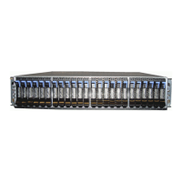
Installing the support rails and enclosure into the rack
Before you can install the control enclosure into the rack, you must rst install the side support rails.
1. At each end of the side rail, grasp the tab and pull rmly to open the hinge bracket.
2. Align the holes in the rail bracket with the holes on the front (1) and rear rack cabinet flanges. Ensure that the rails are aligned on the
inside (2) of the rack cabinet.
3. Close the front hinge bracket (3) to secure the rail to the rack cabinet flange.
4. Extend the length of the side rail, as needed.
5. Close the hinge at the rear of the rail (4).
2