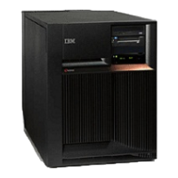
v If you are on a Model 270 system unit, choose from the following options:
– With processor feature 22A2, 22A4, 22A5, 2301, 2302 or 2422, continue with the next step.
– With processor features 22A7, 22A8, 22AA, 22AB, 23F4, 23F5, 2423, 2424, 2454: Go to step 6
(See page 290).
– With processor feature 23E7, 23F0, 23F1, or 2452: Go to step 7 (See page 290).
v
If you are on a Model 800 or 810, choose from the following options:
– With processor features 7428, 7429, or 7430: Go to step 6 (See page 290).
– With processor features except 7428, 7429, or 7430: Go to step 7 (See page 290).
v If you are on a Model 820: Go to step 8 (See page 290).
v If you are on a Model 825: Go to step 9 (See page 291).
v If you are on a Model 830, 840, SB2, or SB3: Go to step 10 (See page 291).
v If you are on a Model 870 or 890: Go to step 15 (See page 292).
5. This is a Model 270 system unit with processor feature 22A2, 22A4, 22A5, 2301, 2302 or 2422. See
Figure 1. Model 270 system unit, processor features 22A2, 22A4, 22A5, 2301, 2302 or 2422 in the
Locations — Model 270 page. Replace the following FRUs in order, one at a time until the problem is
resolved. See the Remove and replace procedures for instructions. Be sure to IPL in SLOW
OVERRIDE mode after each replacement.
a. Power regulator in location R01
b. Power supply in location P01
c. System unit backplane in location MB1
d. Memory card pairs in locations A-H
This
ends the procedure.
6. This is a Model 270 system unit with processor feature 22A7, 22A8, 22AA, 22AB, 23F4, 23F5, 2423,
2424, 2454, or a Model 810 system unit with processor features 7428, 7429, or 7430. See either
Figure 2. Model 270 system unit, processor features 22A7, 22A8, 22AA, 22AB, 23F4, 23F5, 2423,
2424, 2454 in the Locations — Model 270 page, or Locations — Models 800 and 810. Replace the
following FRUs in order one at a time until the problem is resolved. Be sure to IPL in SLOW
OVERRIDE mode after each replacement.
a. Processor card in location M02
b. Power supply in location P01
c. System unit backplane in location MB1
d. Memory riser card in location M01
This ends the procedure.
7. This is a Model 270 system unit with processor feature 23E7, 23F0, 23F1, or 2452, or a Model 800
or 810 system unit with processor features except 7428, 7429, 7430. See either Figure 3. Model 270
system unit, processor features 23E7, 23F0, 23F1, 2452 (Processor embedded on backplane) in the
Locations - Model 270 page, or Locations - Models 800 and 810. Replace the following FRUs in order
one at a time until the problem is resolved. See the Remove and replace procedures. Be sure to IPL
in SLOW OVERRIDE mode after each replacement.
a. Power regulator in location R01
b. Power supply in location P01
c. System unit backplane in location MB1
d. Memory card pairs in locations A-H
This ends the procedure.
8. This is a Model 820. See Locations — Model 820 and replace the following FRUs in order one at a
time until the problem is resolved. Be sure to IPL in SLOW OVERRIDE mode after each replacement.
a. Processor card in location M03
b. Power supply in location P01
c. Power supply in location P02
290 iSeries: iSeries Server 270, 800, 810, 820, 825, 830, 840, 870, 890, SB2, and SB3 Hardware Problem Analysis and
Isolation
 Loading...


