Chapter 4. Using Ultrium media
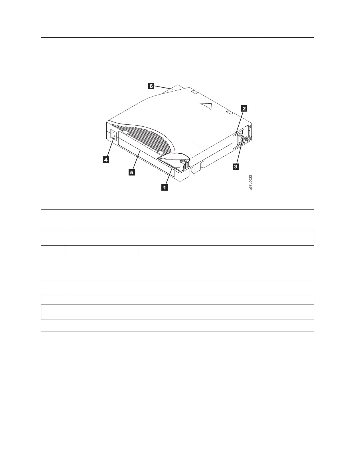
1 LTO cartridge memory A chip that contains information about the cartridge and the tape, as well
as statistical information about the cartridge use. (For more information,
see “Cartridge Memory chip (LTO-CM)” on page 38.)
2 Cartridge door Protects the tape from contamination when the cartridge is out of the
drive.
3 Leader pin The tape is attached to a leader pin, behind the cartridge door. When the
cartridge is inserted into the drive, a threading mechanism pulls the pin
(and tape) out of the cartridge, across the drive head, and onto a
non-removable take-up reel. The head can then read or write data from or
to the tape.
4 Write-protect switch Prevents data from being written to the tape cartridge. (For more
information, see “Write-protect switch” on page 38.)
5 Label area Provides a location to place a label.
6 Insertion guide A large, notched area that prevents the cartridge from being inserted
incorrectly.
Types of cartridges
Ultrium media is available in the following types:
v “Data cartridge”
v “WORM (Write Once, Read Many) cartridge” on page 39
v “Cleaning cartridge” on page 40
Data cartridge
All generations of Ultrium data cartridges contain a half-inch, dual-coat,
metal-particle tape. When processing tape in the cartridges, Ultrium Tape Drives
use a linear, serpentine recording format.
Figure 7. The LTO Ultrium Data Cartridge
© Copyright IBM Corp. 2011 37
 Loading...