The following table provides location codes for parts in a server.
Table 12. FRU location table
Failing item name Physical location code Identify LED
Failing item
removal and
replacement
procedures
System unit Un
Fans
Fan 1 Un-A1 Yes See Fans.
Fan 2 Un-A2 Yes
Fan 3 Un-A3 Yes
Fan 4 Un-A4 Yes
Fan 5 Un-A5 Yes
Fan 6 Un-A6 Yes
Fan 7 Un-A7 Yes
Power supplies
Power supply 1 Un-E1 Yes See Power
supplndary.
Power supply 1 - Cord connector Un-E1-T1 No
Power supply 2 Un-E2 Yes
Power supply 2 - Cord connector Un-E2-T1 No
Backplanes
System backplane Un-P1 Yes See System
backplane.
Time-of-day Un-P1
Time-of-day battery Un-P1-E1 See Time-of-day
battery.
Storage backplane interposer Un-P2 Yes
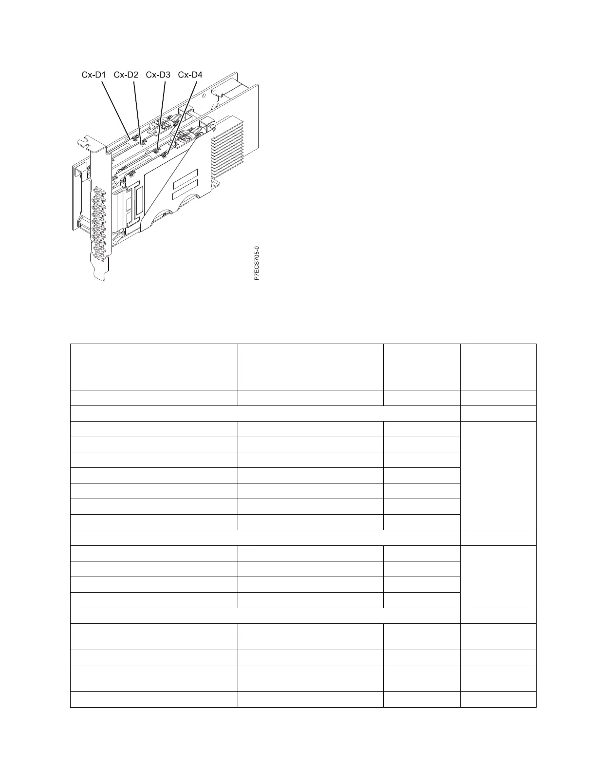
Figure 29. PCIe SAS RAID and SSD adapter locations
Finding parts, locations, and addresses 41

 Loading...


