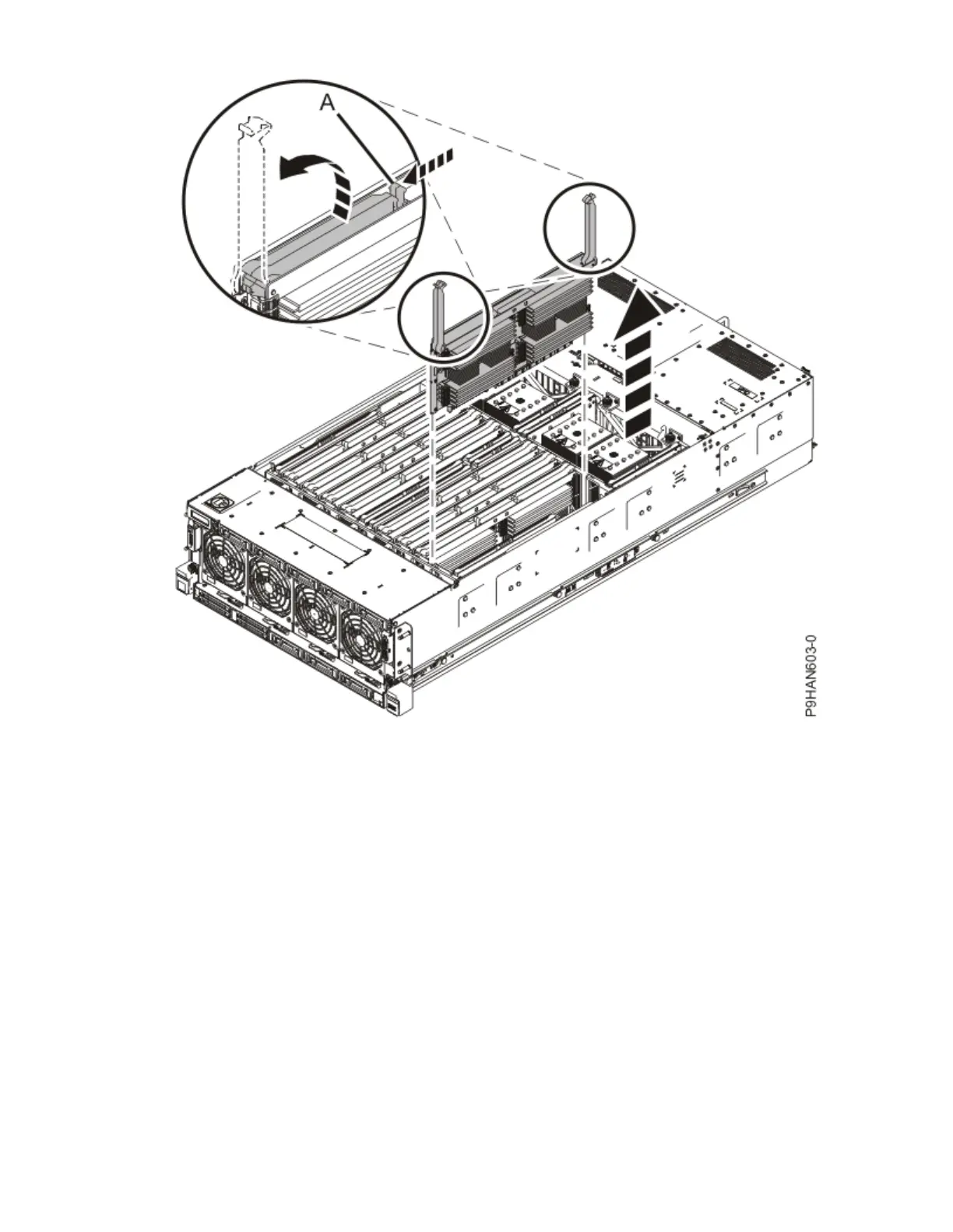
Figure 4. Removing a memory riser
Installing memory modules in the 9040-MR9 system
To install memory module into a memory riser, complete the steps in this procedure.
Procedure
1. Ensure that you have the electrostatic discharge (ESD) wrist strap on and that the ESD clip is plugged
into a ground jack or connected to an unpainted metal surface. If not, do so now.
2. Use the slot information that you recorded to determine the slot location to place the memory module.
3. If the slot you want to use contains a ller, remove the ller from the slot. Push the locking tabs (A)
away from the ller.
Note: The memory module slots must contain either a memory module or a ller to ensure proper
cooling.
To remove the memory module ller, complete the following steps:
a) To unlock the memory module ller from its connector in the slot, push the locking tabs away from
the memory module ller. If you nd it hard to open the tabs with your ngers, you may use the tips
of ball point pens, or the eraser ends of pencils.
The lever action of the tabs pushes the memory module ller out of the connector.
b) Hold the memory module ller by the edges and pull it out of the system.
8
Power Systems: Power Systems: Memory