5. Record and tag each cable that connects to the circuit breaker panel with its
location so you can reinstall them correctly later.
6. Disconnect all cables that connect to the circuit breaker.
Note: If you are removing the bottom circuit breaker panel, you may wish to tag
and disconnect the cabling from the top circuit breaker panel to allow
easier access.
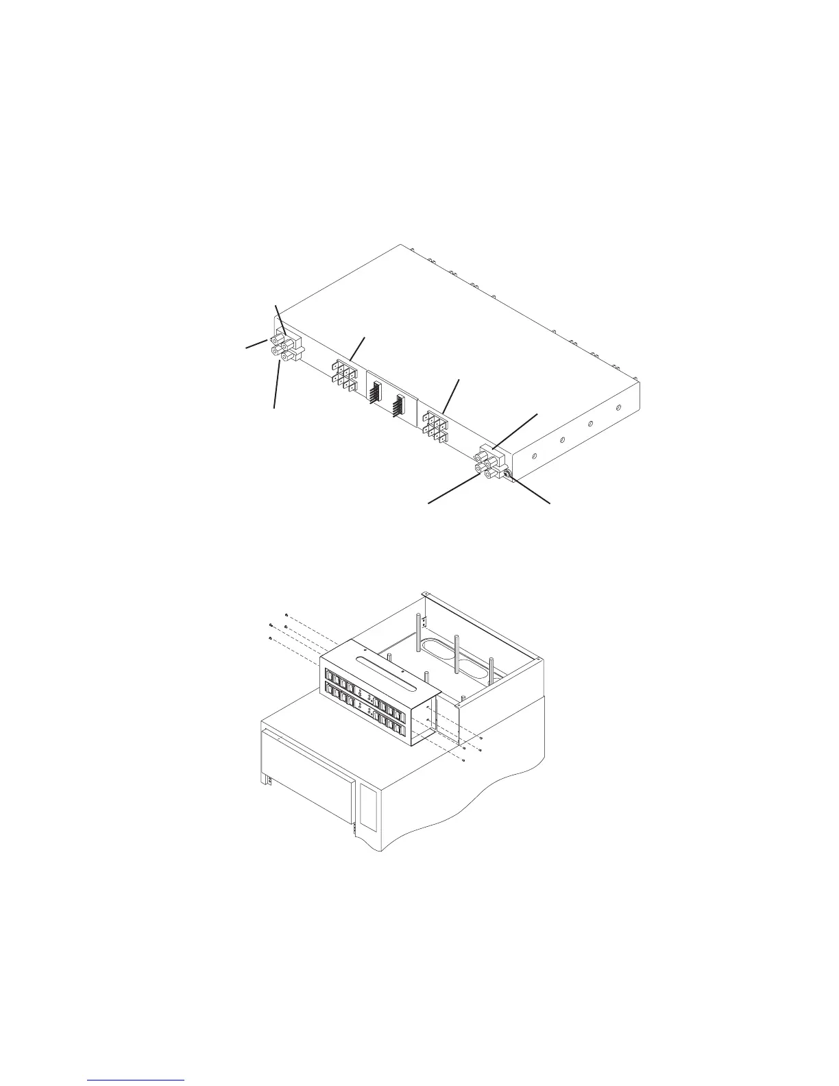
Device
Connections
(Bank B)
Device
Connections
(Bank A)
-48 V DC Input
(Bank B)
-48 V DC Input
(Bank A)
Positive Ground
(Bank B)
Positive Ground
(Bank A)
Ground Cable
Connector
Ground Cable
Connector
(not pictured)
7. Remove two mounting screws from each side of the circuit breaker panel.
8. Slide the circuit breaker panel out the front panel of the chassis.
4-24 7014 Model S00 Rack Installation and Service Guide
 Loading...


