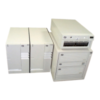
Circuit Breaker Box Replacement
CAUTION:
Energy hazard, remove power before servicing. Disconnect two power supply
cords.
1. If the top cover of the circuit breaker panel chassis is installed, remove the five
mounting screws and remove the top cover.
2. Slide the circuit breaker panel into the front panel of the chassis.
3. Lift the back of the circuit breaker panel as needed to align the holes in the sides
of the circuit breaker panel with the holes in mounting tray.
4. Install two mounting screws through the mounting tray into each side of the
circuit breaker panel.
5. Using the tags on the cables or the customer's records as a guide, reinstall all
device, drawer, and grounding cables to the rear of the circuit breaker panel.
6. Ensure that the customer's technician properly connects the -48 V DC power
cables and return power cables to both circuit breaker panels.
7. Install the top cover of the circuit breaker panel chassis using the five mounting
screws provided.
8. Remove the power-off warning tag or label from the switch for the customer's -48
V DC power source.
9. Switch on the customer's -48 V DC power source.
10. Switch on power to the devices and drawers in the rack. See the service guide
for the CPU enclosure installed in your rack, service guide for the system
installed in your rack, and service guide for the drawers installed in your rack for
more information.
Chapter 4. Removal and Replacement 4-25

 Loading...


