Attention: Refer to “Rack safety” on page xx for danger and caution notices
related to rack and cabinet installations.
You can install the rack mount kit in either of two ways:
v To allow the port side of the switch to slide out of the exhaust-air side of the
cabinet. In this installation, the port side of the switch is flush with the edge of
the cabinet.
v To allow the non-port side of the switch to slide out the cool-air side of the
cabinet. In this installation, the port side of the switch is set 7.62 cm (3 in.) back
from the edge of the cabinet, allowing a more gradual bend in the fiber optic
cables.
Time required
Approximately 30 minutes
Items required
You need the following items to install the switch in a slide-rail rack:
v Straight slot screwdriver
v Rack space: 1 EIA unit of rack space, 48.3 cm (19 in.) wide, and 60.96 cm (24 in.)
deep
v One power cord that is provided with the switch
v One power outlet
v Rack mount kit
Attention: Use the exact screws specified in the procedure for use with the switch
chassis. Using screws longer than 3/16 in. can damage the switch. The different
types of screws are listed in Table 3 on page 11.
Note: Make sure that you tighten all screws used in this procedure.
Installation instructions
To install the switch in a slide-rail rack that meets EIA standards, use the following
procedure.
Note: These procedures use parts that are included in the rack-mount kit. These
parts are listed in Table 3 on page 11. The installation procedure
cross-references the items in this table. Be sure to use the referenced parts
when you perform each step.
Before you start the rack-mount installation process, locate the rack-mount slides
and the mounting bracket that are provided in the shipping container.
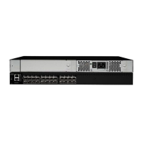
Figure 3 on page 11 shows the rack assembly. The number keys, such as 1, refer
to the items listed in Table 3 on page 11.
10 SAN24B-4 Installation, Service, and User Guide

 Loading...