b. If you have a single node system configuration, use the diagram and the Single System Node to
System Control Unit Table below to determine point to point cabling for the clock flex cables.
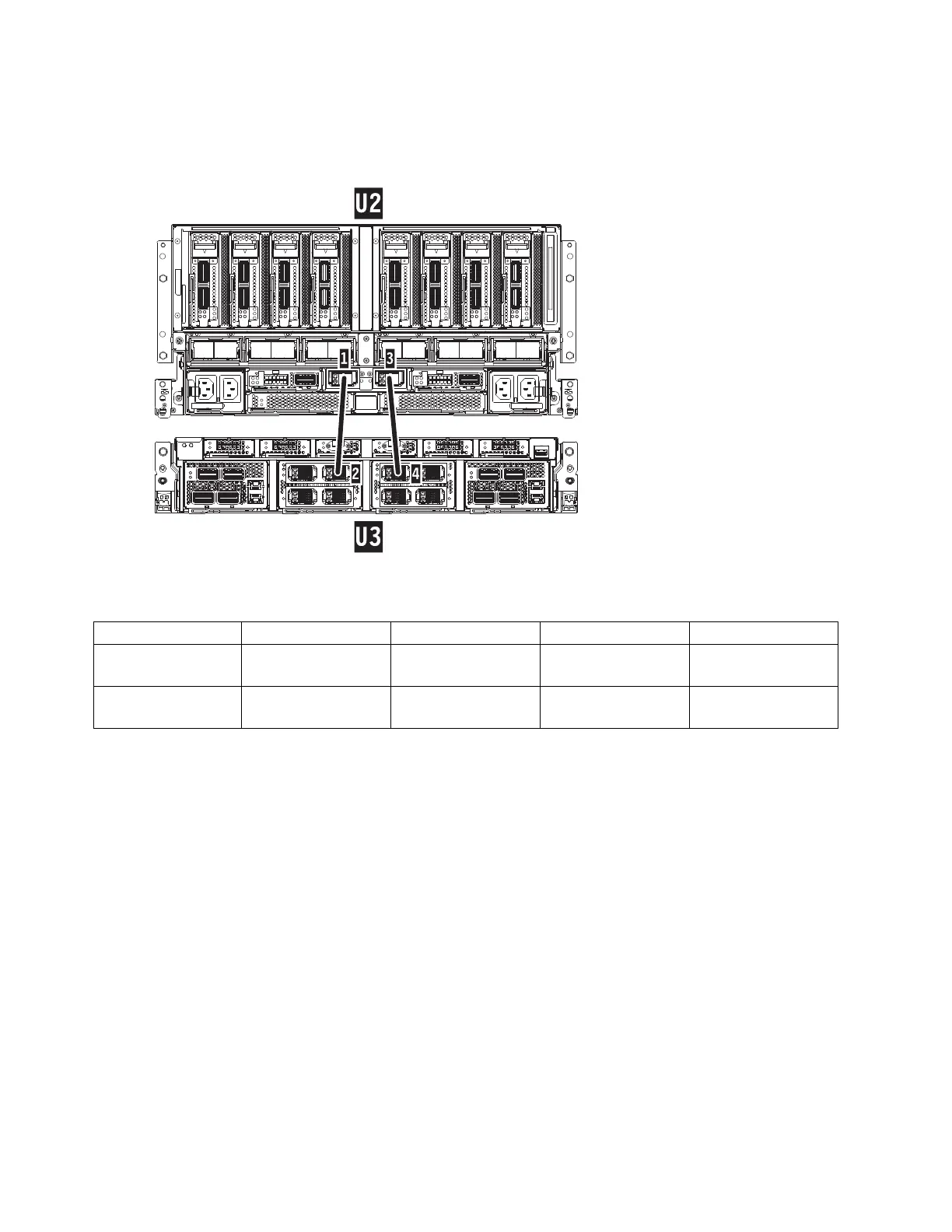
Table 1. Single System Node to System Control Unit Clock Card Cabling
Index Number From: (U-Loc) Cable Type Index Number To: (U-Loc)
1 U2: P1-T7 Short Clock Flex
Cable (Left)
2 U3: P1-C8-T2
3 U2: P1-T8 Short Clock Flex
Cable (Right)
4 U3: P1-C9-T1
c. If you have a two node system configuration, use the diagram and the Two System Nodes to
System Control Unit Table below to determine point to point cabling for the clock flex cables.
32 Power Systems: SCM