1. Read the safety information that begins on page v and “Installation guidelines”
on page 26.
2. Turn off the server and peripheral devices and disconnect the power cords.
Note: When you disconnect the power source from the server, you lose the
ability to view the LEDs because the LEDs are not lit when the power
source is removed. Before you disconnect the power source, make a
note of which LEDs are lit; then, see the Problem Determination and
Service Guide for information about how to solve the problem.
3. Remove the cover (see “Removing the cover” on page 28).
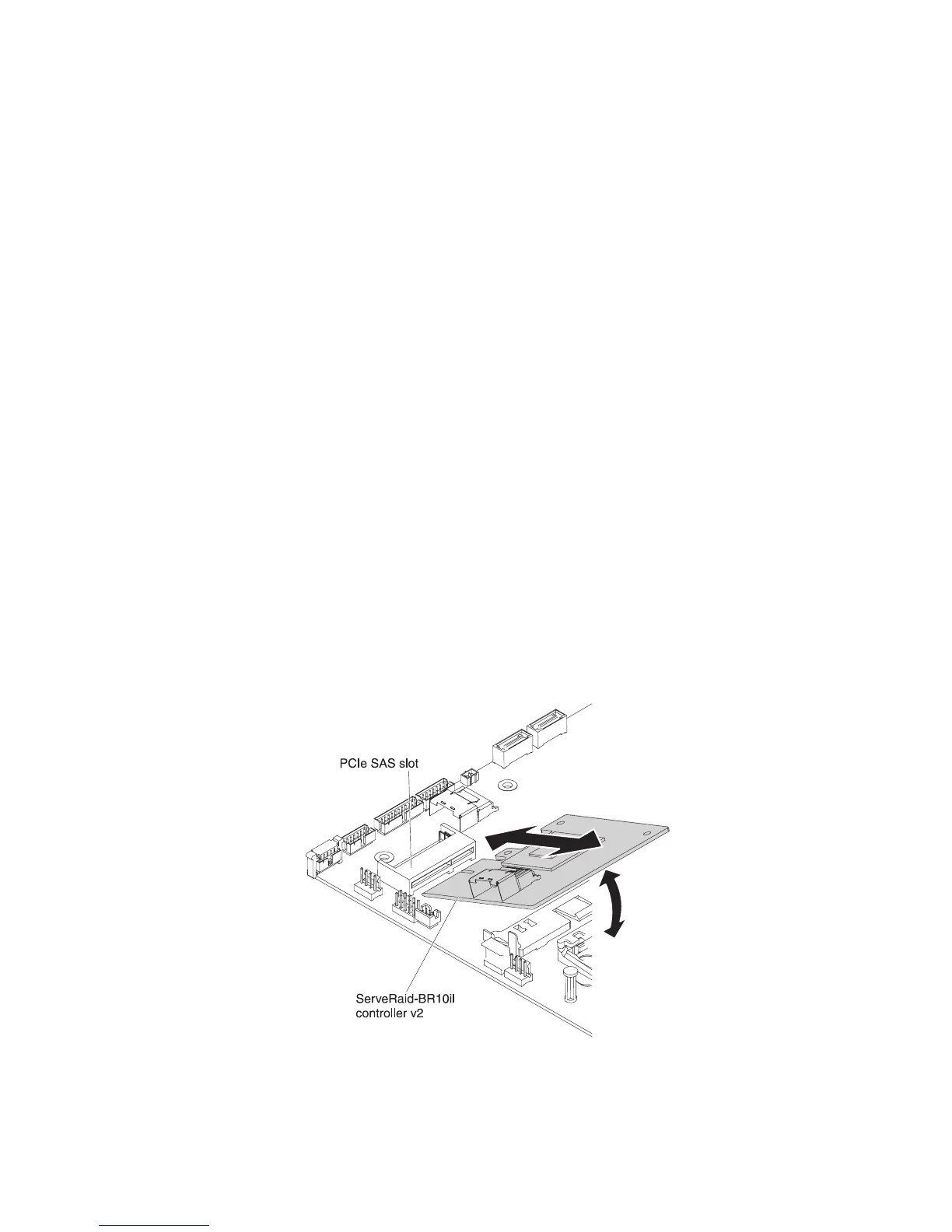
4. Disconnect the signal cables and power cables from the existing SAS/SATA
adapter (if one is installed).
5. Grasp the end of the SAS/SATA adapter next to fan 1 while you press down
the white plastic tab (next to the heat sink) toward the heat sink.
6. Pull the SAS/SATA adapter out from the connector on the system board.
7. Place the SAS/SATA adapter into a static-protective package and put it in a
safe place.
8. Touch the static-protective package that contains the new ServeRAID-BR10il
v2 SAS/SATA adapter to any unpainted surface on the outside of the server;
then, grasp the adapter by the top edge or upper corners of the adapter and
remove it from the package.
9. Align the ServeRAID-BR10il v2 SAS/SATA adapter so that the keys align
correctly with the connector on the system board.
10. Insert the ServeRAID-BR10il v2 SAS/SATA adapter into the connector on the
system board until it is firmly seated. The retention bracket secures the
ServeRAID-BR10il v2 SAS/SATA adapter in place when the adapter is firmly
seated into the connector on the system board.
Attention: Incomplete insertion might cause damage to the server or the
adapter.
11. Route the signal cable from the drive backplane through the fan cage hole
(between fans 1 and 2) as shown in the following illustration.
Chapter 2. Installing optional devices 45

 Loading...


