Do you have a question about the Ice EXTREME AIR FX and is the answer not in the manual?
Game is for indoor use only; proper grounding is essential for safety and operation.
Avoid removing components when powered, always remove power before service, and do not use near water jets.
Details on main fuse type and values for 120V and 230V systems.
Detailed description of each pin on the 9-pin Molex connector for card systems.
Identifies the Molex 9-pin housing required for debit card connections.
Ensure the main PCB battery is enabled and remove any battery block before use.
Game programming is accessed via the PCB for data, free play, and test modes.
Keys are found in the coin return or cabinet bottom for coin and puck doors.
Legs, feet, and hardware are located inside the right side door.
Instructions for attaching feet to legs and securing them with bolts and adjustment rods.
Process of attaching the assembled legs to the cabinet base using 7/16 bolts.
Guidance on flipping the table onto its legs with four people.
Steps to unlatch the cabinet top via puck doors and coin door locks.
The score head assembly attaches to the cabinet bottom; side rails use straps.
Attaching the score head marquee using bolts and connecting the wire harness.
Attaching side guards and playfield divider using specific screws.
Method to enter programming by holding PB3 and navigating with PB2/PB3.
Configuration options for goals, victory mode, game time, and coin acceptor pulses.
Controls for ticket dispensing, payment timing, and fluorescent light activation.
Settings for LED colors, modes, and selecting event-specific audio tracks.
Adjusting general and event-specific music volumes from 0 to 20.
Setting LED brightness and choosing between color and behavior modes.
Retrieving data like coin counts and ticket dispensed via PB2 in attract mode.
Procedure to set and activate free play, including time limits.
Steps for entering and performing diagnostics in test mode, covering LEDs, coins, and pucks.
List of error codes ER01 through ER06 and their respective causes.
Instructions to restore factory settings using a button combination on the PCB.
Specified durations for warranty coverage on PCBs, motors, and monitors.
Conditions that void the warranty, such as abuse, neglect, or unauthorized repairs.
Procedures for obtaining an RMA, returning defective parts, and shipping responsibilities.
| Players | 1 |
|---|---|
| Genre | Sports |
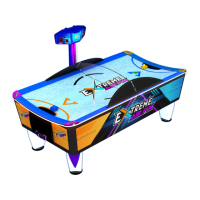
| Model | EXTREME AIR FX |
| Controls | Joystick, Buttons |
| Power Supply | 110V |