MACHINE COMPONENTS
ICE I18B/I18C
6
OPERATOR MANUAL
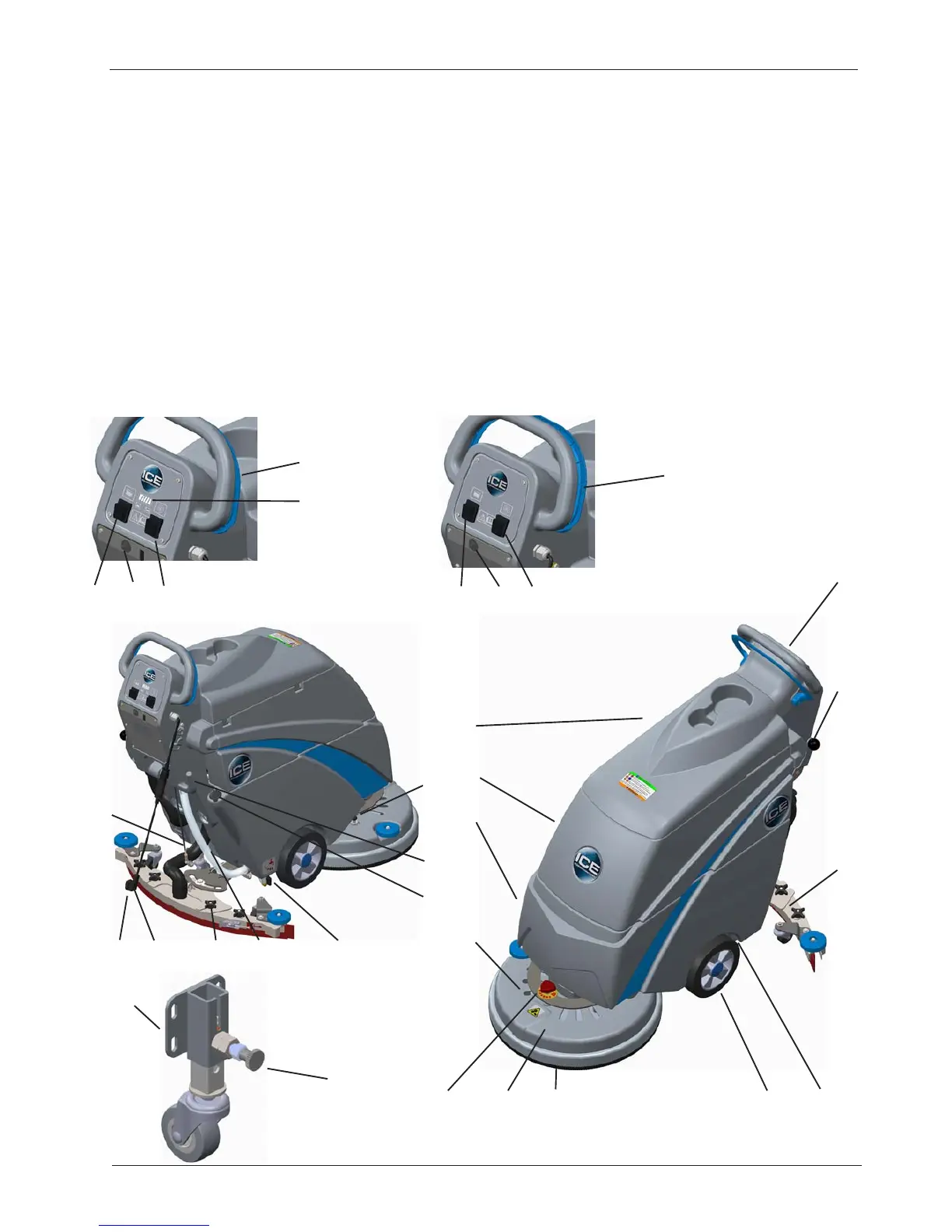
Machine Structure
1. Brush cover 2. Brush 3. Cover tank
4. Recovery tank 5. Solution tank 6. 8" wheels
7. Squeegee 8. Control box 9. Trigger
10. Adjusting handle 11. Water filter 12. Ball valve
13. Squeegee lifting handle 14. Power cord hook 15. Brush/pad driving hub
16. Brush plunger 17. Plug of water filling port 18. Knob
19. Clear tube 20. Switch for brush motor 21. Switch for vacuum motor
22*. Battey monitor 23. Circuit breaker 24*. Charger power cord
24**. Power cord 25. Adjustable wheel 26. Adjusting plunger
1
2
3
4
5
6
7
8
9
10
11
13
12
14
15
17
11
16
18
19
20
20
21
21
22*
23
23
9
24*
24**
I18B I18C
* : only for I18B **:only for I18B
25
25
26