74
ICE I20NB / I20NBT / I24BT
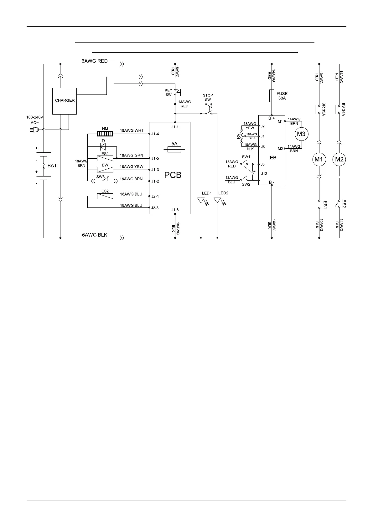
WIRING DIAGRAM
WIRING DIAGRAM FOR I20NBT & I24BT (I20NBT & I24BT)
(SN: i20NBT- 603 i20NBT-OB - 293 i24BT - 320 )
BAT: 2-12V Batteries
CHARGER: On board battery charger
KEY SW: Main power Key switch
HM: Hour meter
D: Diode
ES1: Brush motor solenoid switch
EW: Solution solenoid valve switch
SW3: Safe switch, scrub head lifting
ES2: Vacuum motor relay
PCB: Function electronic board
STOP SW: Emergency stop switch
LED1: Running lights
LED2: Emergency stop lights
RV: Speed potentiometer
SW1: Control handle bail switch, forward
SW2: Control handle bail switch, backward
EB: Speed control board
M3: Transaxle motor
BR: Circuit breaker, Brush motor
BV: Circuit breaker, Vacuum motor
M1: Brush motor
M2: Vacuum motor
 Loading...