13
RESET SHELF EXPLAINED
The main board controls the two shelf motors. Each shelf sensor has its own output back to the
main board. When a sensor is not seen by the game, the game will continue to run the motor until it
times out, making the shelf reset multiple times.
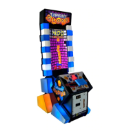
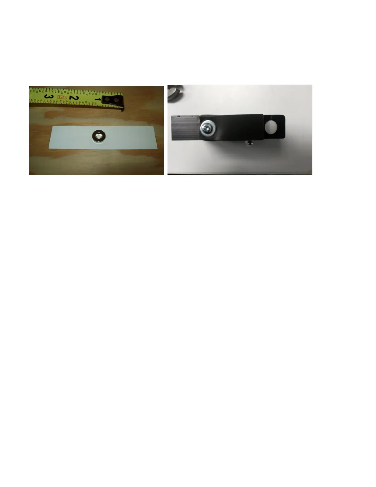
There is a small round metal magnet on the bottom left corner of the shelf.
This magnet must be aligned with the sensor in the shelf rest.
We can verify with an ohm meter that the sensors are working at the main board. Each sensor will
read open or “OL” on your meter when the shelf is up. When the shelf is down the signal will be than
an ohm of resistance.
TOP: Measure at pins 3 and 4 on the J12 connector between the BLUE/BLACK wire
and the BLACK wire.
BOTTOM: Measure at pins 3 and 4 on the J13 connector between the BLUE/WHITE wire
and the BLACK/WHITE wire.
** NOTE ** Balls can unplug sensor wiring if not properly secured.
USING A VOLTAGE METER
You can also measure the voltages present at the main board. At connectors 12 and 13 on the main
board you will find on pin 3 of each connector 0 volts when the shelf is in the home position. When
the shelf moves away from the sensor, the voltage will go to 12 volts. Then when the shelf returns to
the home position, it will go back down to 0 volts. You can use pin 4 for you referenced ground.
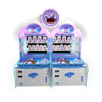
At connectors J9 and 10 on the main board are the clown sense lines. Under each clown is a
magnet. When the clowns are standing up there will be +5 volts of DC on the sense line for that
clown. When the clown is knocked down, the sense line will drop to 0 volts. There are 12 sense
lines in total. J9 is the top row and has 4 sense lines. J10 is for the bottom row and has 5 sense
lines.
 Loading...