Do you have a question about the Icematic M Series and is the answer not in the manual?
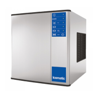
Provides specifications and step-by-step procedures for installation, start-up, and operation of the Modular Cubers.
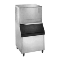
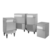
Details the stacking of M 202-302-402-502 models onto Icematic bin model D 201 - D 310.
Specifies refrigerant charge based on the nameplate rating for proper system functioning.
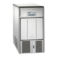
Describes the furnished legs that screw into mounting sockets on the cabinet base.
Outlines minimum and maximum ambient and water temperatures, and water pressure limits.
Guides the selection of a suitable installation location, considering environment and utilities.
Explains the process of laying the bin on its back and screwing in the legs for setup.
Recommends using a mechanical lift and removing panels for installing the icemaker onto the bin.
Instructs on installing the air baffle on the back side of the machine to prevent hot air recirculation.
Details water inlet requirements, including codes, supply, clarity, and pressure.
Describes drain fittings for air-cooled, water-cooled, and storage bin models.
Covers electrical cord connection, local codes, and proper wiring for safety.
Provides a comprehensive checklist for installation verification before operation.
Explains the initial power-on sequence and component activation for the machine.
Details the process of water filling, pump activation, and ice formation.
Describes the process of releasing ice cubes using hot gas and the harvest assist solenoid.
Explains the refrigeration system's function during the freezing cycle.
Details the water inlet valve and sensor controlling reservoir level.
Explains how the hot gas bypass valve is used to harvest ice.
Describes water system operation during the harvest cycle, including draining.
Outlines the sequence of operations controlled by the electronic board.
Lists various alarm conditions indicated by LED status.
Explains different configurations for the PC Board regarding water filling.
Provides operating data and characteristics for different models.
Describes the front console panel, including LEDs and buttons.
Explains the function and components of the electronic control board.
Details the function of the compressor contactor in the control box.
Describes the sensor that measures ice thickness to initiate harvest.
Explains the magnetic switch that signals the PC Board to restart freezing.
Describes the valve that diverts hot discharge gas for ice release.
Details the sensor that detects condenser temperature variations.
Explains the safety control that cuts out at high pressure.
Describes the valve that maintains constant compressor head pressure.
Explains the system for evenly supplying water to evaporator cells.
Details the valve that flushes out the sump assembly.
Describes the valve that regulates refrigerant flow to the evaporator.
Explains the water pump's role in priming and circulating water.
Details the valve that controls water level in the sump.
Describes the sensor that controls water level in the sump.
Explains the board that bypasses the delay time.
Details the switch to bypass the start-up delay.
Describes the solenoid operated in parallel with the hot gas valve.
Lists maintenance tasks for the icemaker, to be scheduled twice a year.
Advises on regular cleaning and sanitizing of the ice storage bin interior.
Provides instructions for cleaning the unit and bin cabinet exteriors.
Details the step-by-step procedure for cleaning the machine using citric acid.
| Type | Modular Ice Maker |
|---|---|
| Ice Type | Cube |
| Condenser | Air-cooled |
| Water Supply | Potable water supply required |
| Material | Stainless Steel |