Do you have a question about the Icematic F 80 C and is the answer not in the manual?
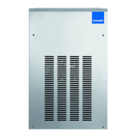
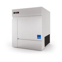
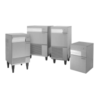
Provides specifications, introduction to modular icemakers, and details on various auxiliary storage bins.
Guides on visually inspecting the icemaker packaging, reporting damage, and removing protective materials.
Provides detailed steps for unpacking and installing various storage bin models, including specific parts and fittings.
Outlines criteria for selecting an installation location and instructions for levelling the storage bin assembly.
Details requirements for electrical connections, including voltage variation, grounding, and circuit protection.
Explains how to connect water supply and drain lines for both air and water-cooled models, including precautions.
Provides a checklist of essential items to verify before the ice maker is put into operation.
Outlines the practical steps for installing the ice maker, covering connections and checks.
Details the step-by-step process for powering on the ice maker, including initial LED indications and component activation.
Guides on performing checks for refrigerant pressures and water level sensor functionality after initial start-up.
Explains how the optical ice level control functions to stop the machine when the ice bin is full.
Describes how water enters, is stored, and circulates within the ice maker's freezing cylinder.
Details the path and state changes of the refrigerant through the compressor, condenser, and evaporator.
Explains the gear motor assembly, auger rotation, and potential issues like wrong rotation or low speed.
Describes the function and operation of the sensor that detects refrigerant temperature in the evaporator.
Explains the two-rod system that detects water presence in the reservoir and prevents operation without water.
Details the sensor that monitors condenser temperature and controls fan operation or unit shut-off.
Describes the safety sensor that monitors drive motor speed and direction, stopping the unit if abnormal.
Explains the function of the optical sensors that detect when the ice bin is full and stop the machine.
Details the function of the PC Board, its LEDs, jumpers, and connection terminals for sensors and electrical components.
Explains the function of PC Board jumpers (TEST, SYEN, Pro.El.Ind.) and the interface board for SFN1000.
Describes the float reservoir, float valve, and water level sensor pins for controlling water supply.
Details the construction and function of the freezing cylinder, auger, and ice breaker, including lubrication advice.
Explains the construction and lubrication of the gear motor, including its bearings and seals.
Describes the air-cooled fan motor control and the water-cooled water regulating valve functions.
Explains the role of the hermetic compressor in circulating and compressing the refrigerant throughout the system.
Provides instructions and diagrams for correctly adjusting the water level in the freezing cylinder.
Details the steps for removing and replacing the magnetic sensor for the gear motor.
Outlines the procedure for replacing the auger, water seal, bearings, and coupling components.
Continues the detailed steps for removing and replacing the auger, ice breaker, water seal, and bearings.
Provides instructions for removing and replacing the entire gear motor assembly, including its base and adaptor.
Details the steps for removing the freezing cylinder, including refrigerant recovery and system evacuation.
Presents the electrical schematic for F120-F200 models, showing connections for sensors, motors, and control board.
Provides the electrical schematic for SF300-SF500 single-phase models, detailing component connections.
Shows the electrical schematic for SF500 three-phase models, illustrating connections and control logic.
Presents the electrical schematic for the SFN1000 model, including interface board and sensor connections.
Lists common ice maker problems, their potential causes, and recommended corrective actions.
Addresses issues like wet ice, no ice production, water leaks, noise, and gear motor problems with solutions.
Provides general advice on maintenance periods, procedures, and variability based on local conditions.
Outlines recommended maintenance tasks for the icemaker itself, including sensor checks and cleaning.
Details the steps for cleaning the water system, reservoir, and freezing cylinder using citric acid.
Continues the detailed steps for cleaning the water system, including using sanitizing solution and final rinsing.
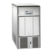
| Production | 80 kg/24 h |
|---|---|
| Ice Type | Cube |
| Voltage | 220-240 V |
| Power Supply | 220-240V |
| Frequency | 50 Hz |