After 3 minutes theunit resumesits total operation
w
ith the immediate start-up of the gear motor
and, few seconds later, of the compressor.
F. Check for the correct operation of the
electronic eye (one per each ice chute on model
M
F 66) of the optical ice level control, by closing
t
he bottom opening of the vertical ice chute.
Wait the built up of the ice into the ice chute till it
cuts the light beam of the sensing "eyes".
This interruption will cause an immediate blinking
of the Bin Full YELLOW LED located on the front
of the P.C. Board and after about 6 seconds
causes the shutoff of the unit (compressor first
and 3' later the gear reducer) with the
simultaneous lighting (steady) of the Same LED
signalling the full bin situation (Fig.5).
Discharge the ice from the ice chute so to resume
the light beam previously interrupted (YELLOW
LED blinking fast) and after about 6 seconds the
flakerwill re-start - throughthe 3 minutesSTAND-
BY period - with the extinguishing of the YELLOW
LED.
This will cause a gradual decrease of the water
level in the float reservoir and as soon as the
level gets below the two vertical metal pins, the
flaker stops to operate (compressor first and 3'
laterthegearreducer)and theYELLOWwarning
LED will glow to signal the shortage of water
(Fig. 4)
NOTE. The water level sensor detects the
presence of water in the float reservoir and
confirms it to the micro processor by
maintaining a low voltage current flow
between the two metal pins using the water
as conductor.
WARNING. The use of de-mineralized
water (water with no salt content) having
an electrical conductivity lower than 30
μS, will cause break with the consequent
CUT-OUT of the flaker and the glowing of
the YELLOW LED of water shortage, even
with water in the reservoir.
Opening the water supply line shutoff valve to fill
up again the float reservoir, the YELLOW LED
goes off while the RED LED starts blinking.
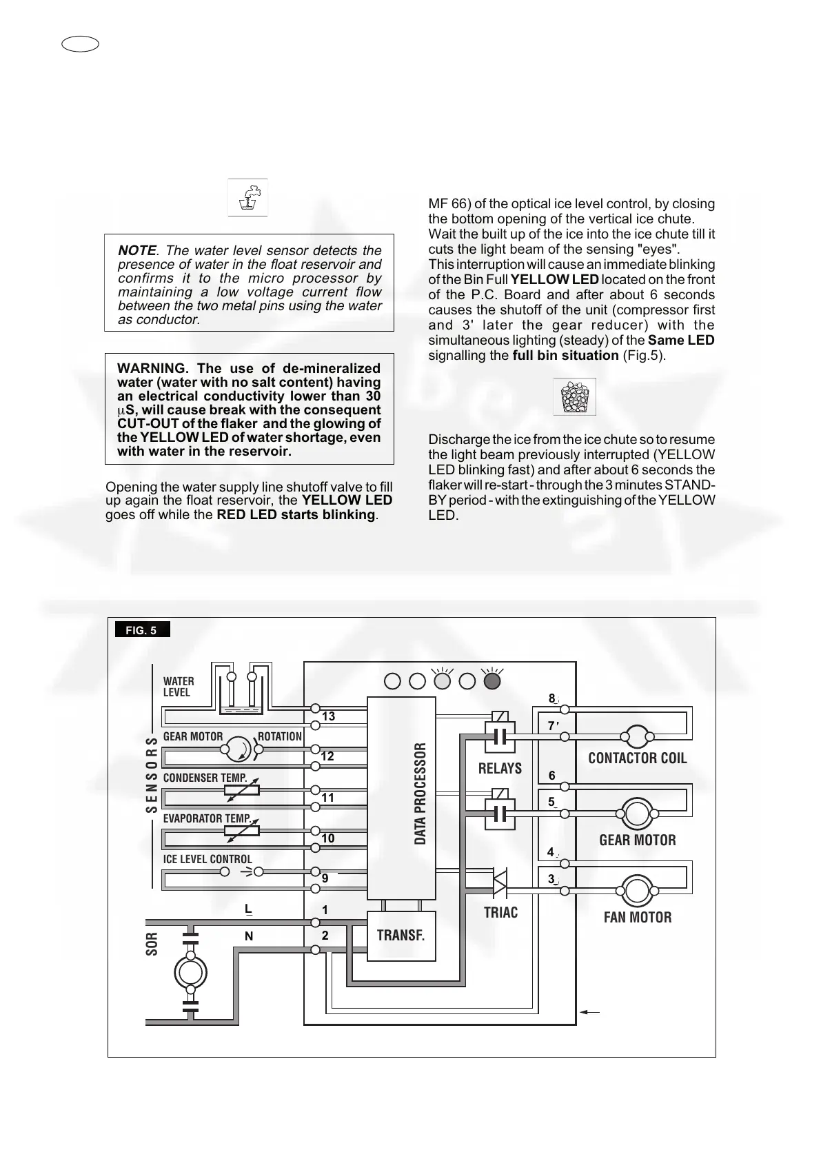
FIG. 5
2
1
L
N
COMPRESSOR
9
10
11
12
13
3
4
5
6
7
8
CONTACTOR COIL
GEAR MOTOR
FAN MOTOR
ELECTRONIC
CARD
RELAYS
TRIAC
RESET
S E N S O R S
WATER
LEVEL
GEAR MOTOR ROTATION
CONDENSER TEMP.
EVAPORATOR TEMP.
ICE LEVEL CONTROL
TRANSF.
DATA PROCESSOR
11
10
9
1
2
L
N
8
7
6
5
4
3
13
12