Installation, Operation & Application Guide
For more information on our complete range of American-made
products – plus wiring diagrams, troubleshooting tips and more,
visit us at www.icmcontrols.com
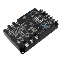
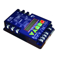
ICM400
Three Phase Voltage Monitor with
Reset Switch
Low cost line voltage protection for
3-phase motor systems
3-Position Reset Switch:
•MAN-MAN
•AUTO-AUTO
•AUTO-MAN
Input
• Line Voltage: Universal, 190-630 VAC • Control Voltage: 18-240 VAC
• Frequency: 50-60 Hz • Frequency: 50-60 Hz
• Load Side Monitoring: Optional
Output
• Type: Relay, SPDT • Voltage Range: 240VAC @ 10A max.
• Frequency: 50-60 Hz
Control Operating Temperature: • Operating Temp:
-40ºF to +167ºF (-40ºC to +75ºC)
• Storage Temp:
-40ºF to +185ºF (-40ºC to +80ºC)
Response Times: • Phase Loss: 2 seconds maximum
• Unbalance/High/Low: Full selected trip delay period
Mechanical: • Mounting: Surface mount using (2) #8 screws
• Terminations: Screw terminals • Weight: 12 ounces (341 grams)
Dimensions: 6 1/2” L, 4 1/4” W, 1 3/8” H (16.5 cm. L, 10.8 cm. W, 3.5 cm. H)
Specification
Phase Unbalance Protection
• Voltage Unbalance: 2-25% adjustable
Over/Under Voltage Protection: • Under Voltage: -12% xed, -6% for reset
• Over Voltage: +12% xed, +6% for reset
Phase Loss Protection
• Phase Loss Condition: Equals 25% of nominal for any given phase; system
will shut down should this occur
Lockout Delay Timer
• Input: 18-240 VAC RMS • Time Delay: .1 to 5 minutes adjustable
• Tolerance: +/-20% • Bypass resistor (24 VAC only): 1 kOhm @ 24 VAC
Fault Interrogation Delay
• Time Delay: 1-15 seconds adjustable
• Provides a delay between fault detection and system shutdown - helps to eliminate
nuisance trips or unnecessary shutdowns
Parameters
Installation of the ICM400 shall be performed by trained technicians only. Adhere
to all local and national electric codes.
Disconnect all power to the system before making any connections.
Caution
Installation
1. Using (2) #8 screws, mount the ICM400 in a cool, dry, easily accessible location in
the control panel enclosure.
2. Connect voltage as shown in Figure 1 (below). Leave existing line and load side
connections intact on the contactor.
Note: Load side monitoring is optional (unit may be used to monitor line side
only).
3. Wire the contactor and control voltage monitoring as in Figures 2 and 3 (below).
Note: Load/line wire must be rated for 3-phase voltage rating, 20ga minimum.
4. Upon application of power, the ICM400 will be online and will begin to monitor the
system.
Incoming 3-phase
voltage from load or
“back” side of contactor
(optional)
LOAD
1
LOAD
2
LOAD
3
LINE 1
LINE 2
LINE 3
Incoming 3-phase
voltage from line or
“front” side of contactor
(190-600 VAC)
Figure 1
• Terminals 4 and 6 are “dry,” normally open contacts
• Terminals 4 and 6 are closed when power is within
specications
• Terminals 4 and 6 open when there is a fault
condition or loss of control signal
Contactor Voltage (18-240 VAC)
Contactor Coil
Figure 3
13
6 5 4
• Terminals 1 and 3 are the control signal input
terminals
• There must be a voltage present on terminals
1 and 3 for the relay output terminals 4 and 6
to close; this voltage can be supplied from a
thermostat, pressure switch, etc.
• When the voltage on these terminals is re-
applied, the unit will not re-energize until
the lockout delay (.1 to 5 minutes) time has
elapsed
Control Voltage
(18-240 VAC)
Short pins when
using 24 VAC
control voltage
with anticipator
type thermostat
Figure 2
* Switch can be
a thermostat,
pressure
switch, etc.
13
6 5 4
3-Position Reset Switch Operation
Choose from three, easy-to-select reset mode positions to best meet the needs of your
system. The modes of operation for each position are described below.
Position 1: FULL MANUAL RESET (MAN-MAN)
Manual control reset required on both the front (line) and back (load) side of system.
Used for highly critical loads. System will not reset until fault is corrected and manually
reset by personnel. After a front side fault the unit will restart only if all of the following
conditions are met:
• The lockout time is complete
• The Reset Mode switch is moved to the AUTO-AUTO position
• No fault condition exists
After a back side fault the unit will restart only if all of the following conditions are met:
• The lockout time is complete
• The Reset Mode switch is moved to the AUTO-AUTO position
• No fault condition exists
Position 2: FULL AUTOMATIC RESET (AUTO-AUTO)
Control automatically resets front (line) and back (load) sides of system. Used on less
critical loads. Helps eliminate unnecessary service calls. After a front or back side
fault, the unit will restart only if all of the following conditions are met:
• The lockout time is complete
• No fault condition exists
Position 3: AUTO FRONT/MANUAL BACK RESET (AUTO-MAN)
Automatic reset on the front (line) side only. Back (load) side requires manual reset.
Typically used with reliable power supply. Back side faults require service evaluation
and manual reset. After a front side fault the unit will restart only if all of the following
conditions are met:
• The lockout time is complete
• No fault condition exists
After a back side fault the unit will restart only if all of the following conditions are met:
• The lockout time is complete
• The Reset Mode switch is moved to the AUTO-AUTO position
• No fault condition exists