Do you have a question about the ICM Controls ICM493-60A and is the answer not in the manual?
Turn off power at the main service panel before installation to avoid electrical hazards.
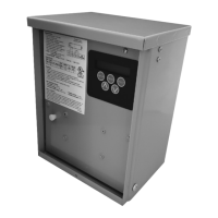
Remove cover and knock-outs, then mount the enclosure to the desired surface with screws.
Lay front panel face down, rotate contactor to access L1, L3, T1, T3 terminal screws.
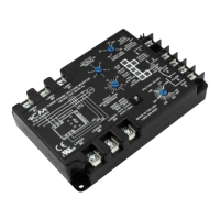
Insert incoming power wires to L1/L3 and load wires to T1/T3 terminals, tightening screws.
Realign contactor, reinsert screws, tilt and align front panel, then attach with screws.
Details on voltage, frequency, FLA, and LRA ratings for the unit.
Covers temperature limits, enclosure type, and physical dimensions.
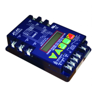
Lists adjustable settings like line voltage, over/under voltage, and delays.
Provides range, default, and recommended values for key parameters.
The ICM493-60A is a programmable, single-phase voltage monitor with surge protection, designed for industrial and commercial applications. It provides comprehensive protection against various power anomalies and offers advanced monitoring and control features.
The device monitors line voltage and protects equipment from over/under voltage conditions, short cycles, and power surges. It features a control board with terminals (T1, T2, T3, T4) for wiring and a user interface for setting parameters and viewing status. The ICM493-60A is designed for outdoor installation and is housed in a NEMA/Type 3R rain-tight enclosure.
| Brand | ICM Controls |
|---|---|
| Model | ICM493-60A |
| Category | Measuring Instruments |
| Language | English |