

H
Heather ClayJul 28, 2025
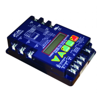
Why does my ICM Controls Measuring Instruments load turn on and off repeatedly?
- AAngela BoyleJul 28, 2025
If the ICM Controls Measuring Instruments load turns on and off repeatedly, it might be due to a load side fault or a delay on break period that is too short. Press the FAULT button to observe the condition. To adjust the delay, press SETUP to enter the delay on break mode, then press the appropriate button to lengthen the delay.