1
Installation
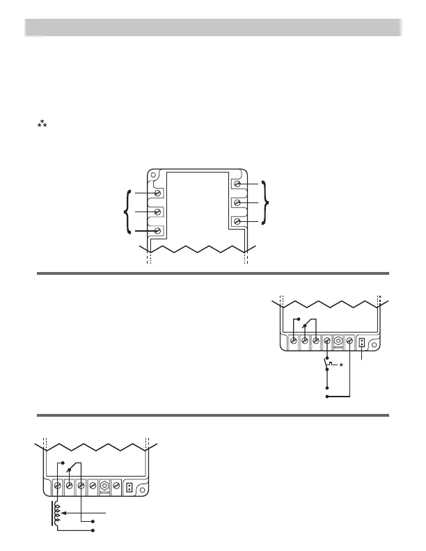
• Terminals 4 and 6 are “dry,” normally open
contacts
• Terminals 4 and 6 are closed when power is
within specifications
• Terminals 4 and 6 open when there is a fault
condition or loss of control signal
Contactor Voltage (18-240 VAC)
Contactor Coil
Figure 3
13
6 5 4
Incoming 3-phase
voltage from load or
“back” side of contactor
(optional)
LOAD
1
LOAD
2
LOAD
3
LINE
1
LINE
2
LINE
3
Figure 1
Incoming 3-phase voltage from
line or “front” side of contactor
The incoming 3-phase voltage is
used to power up the ICM450 as
well (190-600)
1. Using (2) #8 screws, mount the ICM450 in a cool, dry, easily accessible
location in the control panel.
2. Connect voltage as shown in Figure 1 (below). Leave existing line and load
side connections intact on the contactor.
3. Load side monitoring is optional (unit may be used to monitor line side
only). Wire the contactor and optional control voltage monitoring as in
Figures 2 and 3 (below).
Note: Load/line wire must be rated for 3-phase voltage rating, 20ga
minimum.
4. Upon application of power, the ICM450 will be on line and will begin to
monitor the system.
Control Voltage
(18-240 VAC)
Short pins
when using
24 VAC
control
voltage
Figure 2
* Switch can be
a thermostat,
pressure
switch, etc.
13
6 5 4
• Terminals 1 and 3 are the control signal input terminals
• “Control Mode” is turned ON or OFF in setup
• With “Control Mode” set to “ON,” there must be a
voltage present on terminals 1 and 3 for the relay
output terminals 4 and 6 to close; this voltage can be
supplied from a thermostat, pressure switch, etc.
• When the voltage on these terminals is re-applied,
the unit will not re-energize until the delay on break
(0-10 minutes) time has elapsed
• Use of terminals 1 and 3 is optional; they will be
ignored if the “Control Mode” is set to “OFF”