Home
Icom
Transceiver
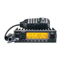
IC-2100H
Icom IC-2100H Service Manual
5
of 1
of 1 rating
30 pages
Give review
Manual
Specs
To Next Page
To Next Page
To Previous Page
To Previous Page
Loading...
4-2
PLL
ADJUSTMENTS
ADJUSTMENT
ADJUSTMENT
CONDITION
MEASUREMENT
VALUE
ADJUSTMENT
POINT
UNIT
LOCATION
UNIT
ADJUST
PLL
LOCK
VOLTAGE
1
•
Displayed
frequency
:
145.000
MHz
•
Receiving
MAIN
Connect
a
digital
multi-meter
or
oscil-
loscope
to
the
check
point
CPI.
1.25-1.30
V
MAIN
L35
2
•
Transmitting
1.45-1.55
V
L2
PLL
REFERENCE
FREQUENCY
1
•
Displayed
frequency
:
145.000
MHz
[EUR,
TPE,
THA]
146.000
MHz
[ITA,
USA,
SEA,
LA]
•
Output
power
:
Low
•
Transmitting
Rear
Pane!
Loosely
couple
the
frequency
counter
to
the
antenna
con-
nector.
145.00000
MHz
[EUR,
TPE,
THA]
146.00000
MHz
[ITA,
USA,
SEA,
LA]
MAIN
C119
DC
power
supply
13.8
V/
20
A
L35
PLL
lock
voltage
adjustment
for
RX
CP1
PLL
lock
voltage
check
point
L2
PLL
lock
voltage
adjustment
for
TX
C119
Reference
frequency
adjustment
4-2
for
free
by
RadioAmateur.eu
10
12
Table of Contents
Table of Contents
3
Pll Circuits
8
Power Supply Circuits
8
Port Allocations
9
Section 4 Adjustment Procedures
10
1 Preparation
10
Pll Adjustments
11
Transmitter and Receiver Adjustments
12
Section 5 Parts List
14
Logic Unit
14
Main Unit
17
Section 9 Block Diagram
27
Other manuals for Icom IC-2100H
Instruction Manual
72 pages
5
Based on 1 rating
Ask a question
Give review
Questions and Answers:
Need help?
Do you have a question about the Icom IC-2100H and is the answer not in the manual?
Ask a question
Icom IC-2100H Specifications
General
Frequency Range
144-148 MHz
Mode
FM
Channels
200
Power Supply
13.8V DC
Antenna Connector
SO-239
Type
Mobile
Dimensions
140 x 40 x 132 mm
Related product manuals
Icom IC-215
15 pages
Icom IC-211E
49 pages
Icom IC-2N
9 pages
Icom IC-28A
70 pages
Icom IC-25A
76 pages
Icom IC-22U
27 pages
Icom IC-230
18 pages
Icom IC-2GAT
62 pages
Icom IC-255A
31 pages
Icom IC-207H
45 pages
Icom IC-2000
39 pages
Icom IC-228A
57 pages