Do you have a question about the Icom IC-251A and is the answer not in the manual?
Details semiconductor count, frequency coverage, resolution, control, readout, stability, memory channels, usable conditions, impedance, power, current, dimensions, and weight.
Covers output power, emission mode, modulation system, frequency deviation, spurious emission, carrier suppression, sideband, microphone, operating modes, and tone burst.
Details receiving system, mode, intermediate frequency, sensitivity, squelch, spurious rejection, selectivity, audio output power, and impedance.
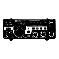
Overview of the IC-251A/E's capabilities including CPU control, scanning, dual VFO, continuous tuning system, and design aspects.
Instructions for unpacking the transceiver, checking for shipping damage, and keeping cartons.
Guidelines for location, ventilation, and connecting AC/DC power supplies.
Guidance on antenna selection, connection, and using an external speaker.
Instructions for connecting audio accessories and CW key, plus grounding.
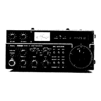
Detailed description of front panel controls like MIC GAIN, RF POWER, POWER SWITCH, PHONES JACK.
Controls for receive mode: MIC connector, SQUELCH, AF GAIN, and RF GAIN.
Controls for MODE SELECT SWITCH and VFO/MEMORY SWITCH.
RIT, Noise Blanker, AGC, T/R, VOX, and Dial Lock controls for signal management.
Tuning speed, memory operations, tuning knob, multi-function meter, and indicators.
Description of rear panel connectors, sockets, and indicators.
Specifics on AC/DC power sockets and the accessory socket.
Fuse holder, key jack, ground terminal, and overview of controls under the access cover.
Controls under the access cover for transmission and signal adjustment.
How to tune, manage preset frequencies, and understand frequency display in different modes.
Using VFOs, dial lock, tuning speed, and basic programmed scan functions.
Programming, reading memory channels, and detailed programmed scan A.
Detailed procedure for programmed scan B.
Setup and usage for SSB receiving, transmitting, and VOX.
Setup and usage for CW receiving, transmitting, monitor, and semi-break-in.
Setup and usage for FM, repeater operation, and VSWR reading.
Table detailing frequencies for AMSAT OSCAR satellites and usage notes.
Diagram and labels for the main PC board components.
Diagram and labels for the PLL unit components.
Table listing common operational problems and their resolutions.
Voltage readings for transistors in the main unit.
Voltage readings for ICs in the main unit during transmit and receive.
Voltage readings for PLL unit transistors and ICs.
Voltage readings for transistors in the driver unit.
Chart for measuring C-MOS and P-MOS IC logic levels.
List and brief description of available optional accessories for the transceiver.
| Power Output | 10 W |
|---|---|
| Power Supply | 13.8 V DC |
| Frequency Range | 144.000-148.000 MHz |
| Mode | FM |
| Sensitivity | 0.25 µV |
| Intermediate Frequencies | 2nd: 455 kHz |