Do you have a question about the Icom IC-251E and is the answer not in the manual?
Details general specifications of the transceiver, including components, frequency, resolution, control, readout, stability, channels, conditions, impedance, power, and current drain.
Covers transmitter specifications such as output power, emission modes, modulation system, frequency deviation, spurious emission, and carrier suppression.
Details receiver specifications including system, mode, frequency, sensitivity, selectivity, squelch, and audio output.
Explains the transceiver's microcomputer control, band-edge detector, endless system, and frequency range for various uses.
Instructions for unpacking the transceiver, checking for damage, and verifying accessories.
Details DC power supply requirements and connection procedures for mobile or external DC use.
Emphasizes antenna importance, recommended types, and proper adjustment for optimal performance.
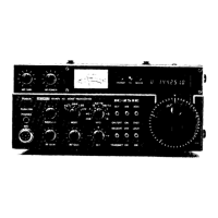
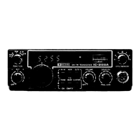
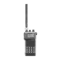
Identifies and describes all controls and indicators located on the front panel of the transceiver.
Selects the operating mode (FM, USB, LSB, CW) for transmission and reception.
Selects between VFO A, VFO B, and activates memory scanning functions.
Allows fine adjustment of the receive frequency relative to the transmit frequency.
Adjusts the operating frequency in specified steps, with an endless system.
Displays RF output power or signal strength depending on the mode.
Shows the current operating frequency and mode indicator.
Identifies and describes connectors and terminals on the rear panel.
Provides general instructions for tuning the transceiver for optimal performance.
Selects between VFO A, VFO B, and various transmit/receive split operations for flexibility.
Guides on receiving and transmitting in Single Sideband (SSB) mode, including USB and LSB.
Details procedures for receiving and transmitting in Continuous Wave (CW) mode.
Guides on receiving and transmitting in Frequency Modulation (FM) mode.
Instructions for setting up and using repeater input/output frequency separations.
A chart listing common problems, their possible causes, and recommended solutions.
Provides voltage readings for transistors in the main unit during transmit and receive modes.
Presents the overall block diagram of the transceiver's internal circuitry.
Explains the operation of the switching regulator circuit for voltage conversion.
Illustrates the functional block diagram of the AC power supply unit.
| Brand | Icom |
|---|---|
| Model | IC-251E |
| Category | Transceiver |
| Language | English |