Do you have a question about the Icom IC-290A and is the answer not in the manual?
Details general specifications like semiconductor count, frequency coverage, resolution, control, readout, stability, memory, conditions, impedance, power, dimensions, and weight.
Covers output power, emission modes, modulation system, frequency deviation, spurious emission, carrier suppression, unwanted sideband, microphone, operating mode, and tone burst.
Details receiving system, mode, intermediate frequency, sensitivity, squelch sensitivity, spurious response rejection, selectivity, audio output power, and impedance.
Explains microcomputer control, band-edge detection, endless system, and frequency coverage for modes like FM, USB, LSB, CW.
Describes Memory Scan and Program Scan features, adjustable speed, and auto-stop functionality.
Explains Dual VFOs for simplex/duplex operation and the Continuous Tuning System with LED display.
Highlights performance aspects like RF amplifier, MOS FETs, and additional circuits like Noise Blanker and CW Break-in.
Instructions for unpacking, checking for damage, and selecting a location for the transceiver.
Details power supply needs, including voltage, current, and negative ground system requirements.
Discusses the importance of a good, high-quality, 50-ohm impedance antenna for performance and tuning advice.
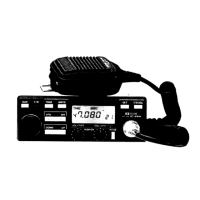
Explains connections for microphone, external speaker, and CW key.
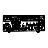
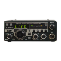
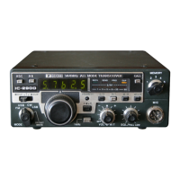
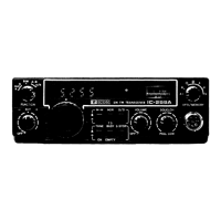
Identifies and explains the functions of front panel controls like MODE SWITCH, TUNING CONTROL KNOB, VFO SWITCH, etc.
Details functions of controls like 1KHz STEPS SWITCH, VOLUME/POWER, RIT CONTROL, and SQUELCH/RF POWER.
Explains switches like PRIORITY, SCAN START/STOP, NB, and indicators like S/RF, PRIORITY, DUPLEX.
Identifies rear panel connectors like ANTENNA, SPEAKER, KEY, POWER, and ACCESSORY sockets.
Details controls located under the top cover for scanning functions like speed and timer.
Explains how to tune, preset frequencies, understand frequency display, and use the tuning control knob.
Explains VFO/Memory switching, frequency transfer, and managing VFO frequencies.
Details offset switch functions for duplex operation, RIT, and resetting offset frequencies.
Step-by-step guide for programming and reading frequencies from memory channels.
Details Memory Scan, Programmed Scan, Full Range Scan, and Resuming Scan functions.
Allows checking a favorite channel periodically while operating on a VFO frequency.
Provides detailed instructions for receiving and transmitting SSB and CW signals, including noise blanker and AGC.
Covers FM reception/transmission, offset settings, and satellite communication procedures.
Identifies and illustrates internal components and adjustment points on the main unit's internal side.
Identifies and illustrates internal components and adjustment points on the PLL unit's internal side.
Explains the PLL, receiver stages (single/dual conversion), RF, and IF circuits.
Details transmitter circuits, detector functions, AF, AGC, noise blanker, squelch, and power supply.
Addresses common issues like power, audio, sensitivity, output, modulation, and operational errors with their solutions.
Presents a comprehensive visual representation of the transceiver's internal architecture and signal flow.
Lists and describes available optional accessories to enhance the transceiver's functionality.
| Brand | Icom |
|---|---|
| Model | IC-290A |
| Category | Transceiver |
| Language | English |