Do you have a question about the Icom IC-27H and is the answer not in the manual?
Details general specifications including semiconductor count, frequency coverage, and resolution.
Transmitter specifications covering output power, emission mode, and modulation.
Receiver specifications detailing sensitivity, selectivity, and audio output.
Highlights compact size, high output power, memory, scanning, tone encoder, and speech synthesizer.
Instructions for unpacking the transceiver and selecting a suitable mounting location.
Details the DC power requirements, voltage, current, and connection precautions.
Guidance on connecting the antenna, microphone, and external speaker for operation.
Describes VFO/Memory, VFO switches, and the tuning control.
Details scan, tuning rate, memory/offset, duplex, and synthesizer/priority buttons.
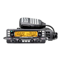
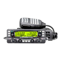
Covers volume, squelch, mic jack, power, tone, and display indicators.
Identifies rear panel jacks and front panel indicators.
Explains CPU reset, scan speed, timer, interval, mode, and function switches.
Instructions for tuning, preset frequencies, and VFO/Memory operations.
How to use simplex, duplex modes, and examples for repeater operation.
Guide to resetting the repeater offset frequency for various separations.
Diagrams showing internal component layout on the main unit side.
Steps for selecting and navigating memory channels.
Programming memory channels and controlling frequency via microphone buttons.
Details Memory, Programmed, Full Range, and Resuming Scan operations.
How to utilize the priority function to monitor channels while in VFO mode.
Instructions for using the subaudible tone encoder and frequency table.
Initial setup and basic operation for receiving signals.
Instructions for transmitting, including simplex, duplex, and microphone use.
Diagrams showing internal component layout on the main unit side.
Diagrams showing internal component layout on the logic unit side.
Troubleshooting steps for power, sound, sensitivity, output, and modulation issues.
Troubleshooting steps for low RF output and modulation problems.
Troubleshooting for contact issues, memory/programmed scan, and scan stop problems.
A block diagram illustrating the transceiver's internal electronic structure.
| Brand | Icom |
|---|---|
| Model | IC-27H |
| Category | Transceiver |
| Language | English |