EasyManua.ls Logo

Icom IC-2710H Service Manual

Icom IC-2710H
48 pages
To Next Page IconTo Next Page
Page #1 background imageLoading...
Page #1 background image
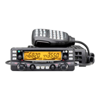
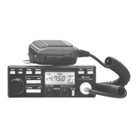
DUAL BAND FM TRANSCEIVER
IC-2710H
lcom Inc.

Other manuals for Icom IC-2710H

Questions and Answers:

Icom IC-2710H Specifications

General IconGeneral
UHF Frequency Range430-450 MHz
Output Power (VHF)50W
ModeFM
Antenna impedance50 ohms
Supply voltage13.8 V DC
Voltage13.8 V DC
Frequency Range430-450 MHz
Output Power (UHF)35 W
Output PowerVHF: 45/5 W, UHF: 35/5 W
Receiver Sensitivity0.16 µV (12 dB SINAD)
RF Power outputVHF: 50 W, UHF: 35 W
Selectivity12 kHz

Summary

General Safety Information

Electrical Hazard Warnings

Avoid high voltage, water, and improper connections to prevent shock or fire.

RF Exposure and Polarity Precautions

Limit RF input and ensure correct power polarity to protect the device.

Specifications

Internal Views - Main Unit

Key Component Identification

Labels for VHF/UHF RF modules, amplifiers, filters, CPU, and regulators.

Disassembly Procedures

Cover Removal Steps

Instructions for safely removing the bottom and main covers.

Speaker and Main Unit Removal

Steps for disconnecting speaker and removing the main unit assembly.

Receiver Circuit Descriptions

Duplexer and Antenna Switching Circuits

Filters and switches RF signals for VHF and UHF band reception.

VHF RF, IF, and Para-Watch Circuits

Details VHF RF amplification, mixing, IF stages, and V/V para-watch function.

2nd IF and Demodulation Circuits

Describes the second IF stage and demodulation process for audio output.

AF Amplifier and Squelch Circuits

Amplifies audio signals and implements noise squelch for VHF/UHF.

UHF RF and Squelch Circuits

Covers UHF RF signal path and noise squelch implementation.

UHF 2nd IF and Detector Circuits

Details UHF second IF stage and detector circuits.

Transmitter Circuit Descriptions

Microphone and Modulation Circuits

Processes microphone audio for signal modulation in VHF/UHF transmitters.

VHF Drive and Power Amplifier Circuits

Covers VHF pre-drive, drive, and power amplifier stages.

VHF APC Circuit Function

Protects power module and drive amplifier from mismatched loads, stabilizes output.

UHF Modulation and Power Amplifier Circuits

Details UHF modulation, drive, power amplification, and APC circuit.

PLL Circuit Operations

VHF PLL Loop Configurations

Explains V-VHF and V-UHF PLL loops for frequency stabilization.

UHF PLL Loop Configurations

Explains U-UHF and U-VHF PLL loops for frequency stabilization.

CPU Port Allocations

Main CPU Port Functions

Describes input/output functions for the main CPU ports.

Sub-CPU Port Functions

Details port functions for the sub-CPU control unit.

Preparation for Servicing

Required Test Equipment

Lists essential test equipment for servicing procedures.

Test Equipment Connection Diagram

Illustrates the setup for connecting test gear for adjustments.

PLL and Transmitter Adjustments

PLL Lock Voltage and Frequency Tuning

Procedures for adjusting PLL lock voltage and reference frequency.

Output Power and Frequency Deviation Adjustments

Steps to set VHF/UHF output power and frequency deviation.

Receiver Adjustments

Sensitivity and Squelch Level Calibration

Adjusts VHF/UHF receiver sensitivity and squelch threshold.

S-Meter Calibration Procedure

Steps to calibrate the S-meter for accurate signal strength indication.

Mechanical Parts and Disassembly

Chassis and Control Unit Parts

Lists mechanical components for chassis and control unit assemblies.

HM-98 Microphone Components

Identifies parts for the HM-98 remote control microphone.

Semiconductor Information

Transistor and Diode Identification

Provides symbols and internal views for transistors and diodes.

Control Unit Board Layouts

Control Unit Top View Layout

Shows the placement of components on the top side of the control unit PCB.

Control Unit Bottom View Layout

Shows the placement of components on the bottom side of the control unit PCB.

Main Unit Board Layouts

Main Unit Top View Layout

Shows the placement of components on the top side of the main unit PCB.

Main Unit Bottom View Layout

Shows the placement of components on the bottom side of the main unit PCB.

Optional Unit - HM-98 Microphone

HM-98 Microphone Circuit Details

Includes schematic, board layouts, and adjustment procedures for the HM-98.

Optional Unit - HM-90 Cordless Microphone

HM-90 Microphone Schematic

Circuit diagram for the HM-90 cordless microphone.

HM-90 Main Unit and Logic Unit Board Layouts

Top and bottom views of HM-90 main and logic unit boards.

HM-90 Switch Board Layout

Top view of the switch board for HM-90.

HM-90 Adjustment Procedures

Details adjustments for microphone output, reference frequency, and deviation.

Optional Units - BC-96 Holder & UT-104 Squelch

BC-96 Holder Board Layout

Top and bottom views of the BC-96 microphone holder board.

UT-104 Squelch Unit Board Layout

Top and bottom views of the UT-104 tone squelch unit board.

Optional Unit - EX-1759 Receiver

EX-1759 Receiver Adjustment Procedures

Instructions for adjusting squelch, busy, and rectangle waves.

Block Diagram

Voltage Diagrams

Related product manuals