Do you have a question about the Icom IC-275E and is the answer not in the manual?
Lists the accessories included with the IC-275A/E transceiver and instructions for manual handling.
Controls the input power to the IC-275A/E transceiver.
Adjusts audio output level and squelch threshold; clockwise rotation increases level.
Accepts headphones (4-16 ohm) and connects a suitable microphone.
Selects operating modes: FM, USB, LSB, or CW.
Controls speech compressor, receiver preamplifier, and AGC time constant.
Reduces pulse noise and enables Tone Squelch function.
Sets tone frequency, duplex mode, and manually switches transmit/receive.
Selects meter function and controls RF output power.
Details on Readout, Tone Squelch, Duplex, Split, Scan, RIT, Skip, Memory, VFO, Data, and Mode indicators.
Details AC/DC power sockets, antenna, remote control, ground, and accessory jacks.
Avoid hot, humid, dusty environments, direct sunlight, and proximity to noise sources.
Connect transceiver to ground terminal for safety and to prevent interference.
Warning about voltages greater than 15V DC and non-ICOM AC power supplies.
Features ICOM DDS (Direct Digital Synthesizer) for fast lockup times.
Built-in 99-channel memory and advanced remote control system via RS-232C.
Features a soft orange illuminated LCD for visibility in bright conditions.
Includes Memory, Programmed, Selected Mode Memory, and Skip Scan.
Includes Passband Tuning (PBT) and Notch Filter for interference reduction.
Utilizes low noise figure GaAs-FET amplifier and balanced-type mixer.
Designed for versatile VHF operation.
Compact dimensions simplify installation in mobile and portable situations.
Supports PACKET/AMTOR via rear panel terminal socket and [DATA] SWITCH.
Provides smooth, fast, and natural CW conversations.
Lists optional units like preamplifiers, synthesizers, and filters.
This is a push-lock switch which controls the input power to the IC-275A/E.
This control varies the audio output level. Clockwise rotation increases the level.
Sets the squelch threshold level. Counterclockwise to turn OFF.
Accepts a standard 1/4 inch plug from headphones with an impedance of 4-16 ohm.
Connect a suitable microphone to this connector.
Select any of the four operating modes: FM, USB, LSB, or CW.
This switch turns the built-in speech compressor circuit ON and OFF.
Turns the receiver preamplifier ON and OFF when the optional AG-25 is installed.
Changes the time constant of the AGC circuit (Slow or Fast).
Reduces pulse-type noise generated by automobile ignition systems.
Turns the Tone Squelch function ON/OFF (requires optional UT-34).
Used with [TONE] switch for setting subaudible tone frequency.
Activates subaudible tone circuit (USA) or 1750Hz tone call (Europe).
Selects simplex or duplex mode operation.
Monitors transmit-frequency when duplex mode is selected.
Manually switches transceiver between transmit and receive.
Selects meter function for receiving or transmitting.
Controls RF output power from 2.5W to maximum continuously.
Varies RF stage gain in receive mode; attenuates signals by 20dB in FM mode.
Changes transmit-receive switching time during CW operation.
Adjusts receive audio tone for clarity and pleasing sound.
Adjusts modulation level for suitable voice input.
Activates optional UT-36 Speech Synthesizer for announcements.
Starts and stops all IC-275A/E scan functions.
Turns the SELECTED MODE MEMORY SCAN function ON and OFF.
Sets the skip channel to be skipped in MEMORY SCAN.
Enables digital communications (PACKET/AMTOR) with time delay.
Increases/decreases frequency; quick rotation for 10kHz, slow for 2.5kHz.
Increases tuning step by 1kHz; push again to return to previous step.
Sets the tuning step rate for 1MHz steps.
Selects VFO A or VFO B for tuning, or switches between VFO/MEMO/CALL modes.
Sets transmit/receive relationship between VFOs for duplex/simplex.
Electronically locks display and deactivates tuning control.
Selects the CALL CHANNEL most frequently used as a call frequency.
Transfers memory channel frequency/mode to VFO, or vice versa.
Instantly matches frequency and mode of operation of the two VFOS.
Turns the NOTCH FILTER circuit ON and OFF.
Shifts NOTCH FILTER frequency to reduce or eliminate interfering signals.
Allows continuous tuning of passband selectivity to reduce interference.
Turns the RIT circuit ON and OFF; 'RIT' indicator appears.
Clears frequency shift information and resets incremental tuning to '0.0'.
Shifts receive frequency by up to 9.9kHz from the displayed frequency.
Selects the MEMORY CHANNEL mode; 'MEMO' indicator appears.
Stores displayed information into a memory channel.
Clears unwanted information from a displayed memory channel.
Used for selecting memory channels.
Refer to SECTION 3-2 for more information on the frequency display.
Functions as S-meter, Center meter, RF-meter, or ALC-meter.
Indicators light up when the transceiver is in transmit or receive mode.
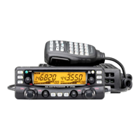
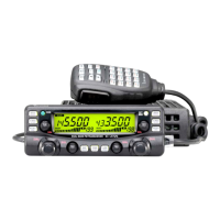
This readout shows the operating frequency using a 7-digit display with 100Hz resolution.
'TONE-S' appears when Tone Squelch is activated with optional UT-34.
Either 'DUP+' or 'DUP-' appears when duplex mode is selected.
'SPLIT' appears when separate VFOs are used for transmit and receive.
'SCAN' appears whenever a scan function is selected.
'RIT' and shift frequency appear when the RIT circuit is activated.
'SKIP' appears when the displayed memory channel is programmed for skip scan.
'MEMO' and memory channel numbers appear in MEMORY or CALL CHANNEL mode.
'VFO A' or 'VFO B' appear, indicating the currently selected VFO.
'DATA' appears when the [DATA] SWITCH is pushed.
This area displays the operating mode currently selected.
Connects the IC-275A/E to AC outlets via the supplied AC cable.
Outputs 13.8V DC and connects to the DC POWER SOCKET.
Holds fuses for AC power supply; used for replacing damaged fuses.
Connects DC power cable from an external AC power supply.
Connect a 50 ohm impedance antenna using a PL-259 plug.
Communications port for personal computer remote operation.
For preventing electrical shocks, TVI, BCI, and other problems.
Provides signals for AQS (Amateur Quinmatic System).
Provides signals such as T/R switching, receiver output, ALC input.
Connects an external speaker (4-16 ohm); built-in speaker is disabled.
Varies the compression level when the [COMP] SWITCH is pushed IN.
Alters the bass and treble response of your transmitted signal.
Selects one of three meter functions in transmit mode (RF, SET, SWR).
Adjusts the audio level of the CW sidetone circuit for monitor volume.
Sets operation to FULL or SEMI break-in CW, or OFF.
Connects a CW key for CW operation using the supplied key plug.
Select a location for access to controls, air circulation, and rear connections.
Details mobile/marine installations using optional mounting bracket.
Importance of antenna performance and VSWR; coaxial cable use.
Step-by-step guide for installing a PL-259 connector on coaxial cable.
Refer to Section 1 for detailed grounding information.
Instructions for DC operation, AC operation with PS-55, and non-ICOM AC supplies.
Details connection for 50 ohm impedance load and ALC input via ACC(1) socket.
Diagrams for connecting AFSK unit via ACC(1) socket or MIC connector.
Details the pin assignments for MIC INPUT, AF OUTPUT, PTT, etc.
Details signals available from ACC(1) socket: NC, GND, SEND, MOD, AF, SQLS, 13.8V, ALC.
Describes functions of AQS system and pin assignments: TX E, TX MOD, MUTE, CAC, RX RF, PTT, SEND, SEARCH, E, CI-V, NC, RECV, 13.8.
Details ICOM CI-V system, interface with RS-232C, and S3 SWITCH settings.
Sets front panel and rear panel switches and controls before operation.
Provides instructions for FM receiving and transmitting.
Adjusts AF/SQL/TUNING controls, selects FM mode, and checks signal strength.
Selects transmit mode, adjusts RF PWR, speaks into mic, and checks modulation.
Procedures for duplex operation using the [DUP] SWITCH and [XMIT].
Adjusts AF/SQL/TUNING controls, selects USB/LSB mode, and uses AGC.
Selects transmit mode, sets meter to ALC, and adjusts MIC GAIN.
Provides instructions for CW receiving and transmitting.
Sets controls, selects CW/N mode, adjusts AGC/AF/SQL/TUNING.
Connects CW key, selects transmit mode, operates key, adjusts RF PWR.
Selects transmit mode via [XMIT] or [BK-IN] switch, operates key, adjusts RF PWR.
Monitors keying with an 800Hz sidetone; adjustable volume.
Handles semi/full break-in capability for CW operation.
Requires rapid transmit/receive switching; uses [DATA] SWITCH for 3msec switching.
Uses AFSK; demodulator needs specific filters for shift operation.
Explains the difference between displayed and actual frequency in RTTY.
Diagrams for connecting RTTY Terminal Unit for AFSK operation.
Slow Scan Television operation is possible; connection via ACC(1) or MIC connector.
Improves intelligibility of transmitted signal for greater talk power.
Activates optional AG-25 PREAMPLIFIER UNIT for receive amplification.
Fast attack/slow release AGC system for peak IF signal voltage.
Reduces unwanted pulse-type noise from outside sources.
Subaudible tone for repeaters (USA) or 1750Hz tone call (Europe).
Example of duplex operation using 145.000MHz receive and 144.4000MHz transmit.
Example for resetting the offset frequency at 850kHz.
Example for 145.9500MHz receive and 144.0500MHz transmit using VFO A/B.
Allows digital communications (AMTOR/PACKET) with time delay.
Narrows bandwidth selectivity to pass desired frequencies.
Provides high attenuation at a frequency to reduce interfering signals.
Shifts receive frequency up to 9.9kHz without moving transmit frequency.
Changes operating frequency or memory channel using microphone UP/DOWN switches.
Checks antenna matching and SWR using built-in SWR meter.
Selects MEMORY CHANNEL mode or returns to VFO A/B mode.
Memorizes frequency, mode, tone, and duplex condition into memory channels.
Sets and stores frequently used frequencies for quick recall.
Recalls programmed CALL CHANNEL information and returns to VFO/MEMO mode.
Clears unwanted information from a selected memory channel.
Scans all programmed memory channels, skipping blank status channels.
Monitors a particular section of the band between P1 and P2 frequencies.
Selectively monitors memory channels with frequencies programmed in the same mode.
Repeatedly scans specific memory channels, skipping chosen channels.
Covers cleaning, fuse replacement, backup battery, and microprocessor reset.
Instructions for replacing blown fuses in the transceiver.
Provides power to retain memory information; lifespan and replacement notes.
Procedure to reset the transceiver, clearing all memory channel information.
Adjusts the tension of the TUNING CONTROL via a screw on the bottom side.
Varies the intensity of the FREQUENCY DISPLAY illumination.
Adjusts the beep sound level emitted when switches are pushed.
Shows internal components and adjustment points on Main and RF-YGR units.
Shows internal components and installation spots for optional units.
Steps for removing top cover, bottom cover, and PA UNIT.
Instructions for installing the UT-34 unit and its connections.
Instructions for installing the UT-36 unit on the bottom side.
Installation details for the FL-83 CW Narrow Filter on the MAIN UNIT.
Installation details for the CR-64 High-Stability Crystal Unit on the MAIN UNIT.
Provides a detailed block diagram of the IC-275A/E's internal circuitry.
Lists and illustrates various optional accessories for the IC-275A/E.
Space to record serial number, date of purchase, and place of purchase.
| Mode | FM |
|---|---|
| Image rejection | 70 dB |
| IF rejection | 70 dB |
| Spurious rejection | 70 dB |
| Voltage | 13.8 V DC ±15% |
| Power Supply | 13.8 V DC |
| Frequency Range | 144-148 MHz |
| Sensitivity | 0.25 µV (12 dB SINAD) |