Do you have a question about the Icom IC-275A and is the answer not in the manual?
Lists accessories included with the IC-275A/E transceiver for unpacking.
Guidelines for selecting a suitable and safe environment for transceiver placement.
Instructions for proper grounding to prevent electrical hazards and interference.
Warning regarding DC voltage limits for the transceiver and power supply connection.
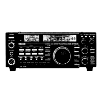
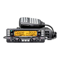
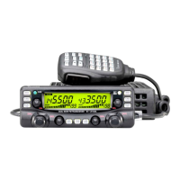
Detailed description of front panel switches, controls, and frequency display indicators (Items 1-61).
Describes rear panel connectors and additional functions like speaker and break-in switches (Items 62-76).
Guidelines for planning installation and mounting the transceiver.
Importance of antennas, grounding, and PL-259 connector installation.
How to connect DC and AC power supplies to the transceiver.
Connecting linear amplifiers, AFSK units, MIC, ACC(1), and AQS sockets.
Explains the CI-V system and connections for remote control via RS-232C.
Steps for initial setup and operating in FM mode.
Procedures for receiving and transmitting in SSB and CW modes.
How to operate PACKET, AMTOR, RTTY, and SSTV modes.
Using speech compressor and receiver preamplifier functions.
Details on Noise Blanker, Subaudible Tone, 1750Hz Tone Call, and Duplex operations.
Using Passband Tuning, Notch Filter, and RIT for signal clarity.
Using microphone controls and checking antenna SWR.
Overview of the four scanning functions available on the transceiver.
How to select memory channels and switch between VFO A and VFO B.
Step-by-step guide to storing frequencies and modes into memory channels.
How to program and recall specific call frequencies for quick access.
Procedures for clearing unwanted data from memory channels.
Details on Memory Scan, Programmed Scan, Selected Mode Scan, and Skip Scan.
Procedures for cleaning, fuse replacement, backup battery, and microprocessor reset.
How to adjust tuning control tension, display brightness, and beep sound level.
Diagrams showing the layout of the main and RF-YGR internal units.
Diagrams showing the layout of the PLL and Logic internal units.
Steps for disassembling the transceiver to access internal units for option installation.
Installation guides for Tone Squelch, Voice Synthesizer, CW Filter, and Crystal Unit.
| Frequency Range | 144-148 MHz |
|---|---|
| Weight | 4.5 kg |
| Image Rejection | 70 dB |
| IF Rejection | 70 dB |
| Spurious Rejection | 70 dB |
| Power Supply | 13.8 V DC |
| Mode | FM |
| UHF Frequency Range | 430-440 MHz |