Do you have a question about the Icom IC-271A and is the answer not in the manual?
Provides detailed specifications for the transceiver, covering frequency, control, and power.
Details the specifications related to the transmitter section of the transceiver.
Details the specifications related to the receiver section of the transceiver.
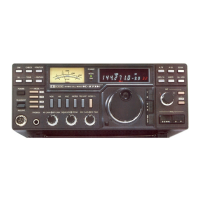
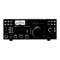
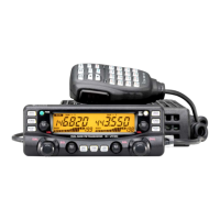
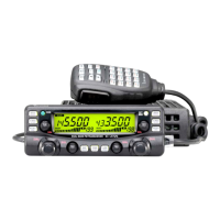
Describes the functions and operations of the front panel controls.
Details the rear panel connectors, their pin assignments, and functions.
Presents the functional block diagram for the IC-271A/E model.
Presents the functional block diagram for the IC-271A/H model.
Presents the functional block diagram for the IC-271H model.
Describes the PA unit's antenna switching circuit and its operation.
Describes the circuitry and functions of the RF/YGR unit.
Details the power amplifier stage of the transceiver.
Details the Central Processing Unit (CPU) and its role.
Covers RF meter, SWR detector, and protector circuits.
Outlines essential safety and preparation steps before performing maintenance.
Provides detailed procedures and settings for adjusting the Phase-Locked Loop (PLL).
Details the procedures for calibrating and adjusting the transmitter section.
Covers the adjustment procedures for setting the transceiver's output power.
Details the procedure for adjusting the RF meter for accurate readings.
Covers the adjustment procedure for the tone level control.
Provides instructions for calibrating and adjusting the receiver section.
Specifications for the SC-1013 110W VHF RF Power Amplifier.
Specifications for the SC-1020 25W VHF RF Power Amplifier.
Presents the overall schematic diagram for the IC-271A/E transceiver.
Presents the overall schematic diagram for the IC-271H transceiver.
| Brand | Icom |
|---|---|
| Model | IC-271A |
| Category | Transceiver |
| Language | English |