


C
Cheryl CookAug 15, 2025
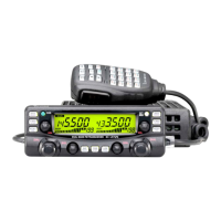
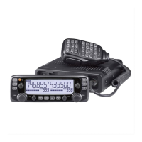
What to do if only 1 memory channel is programmed on Icom IC-2720H Transceiver?
- SSandra KingAug 15, 2025
If only 1 memory channel is programmed or other channels are set as skip channels on your Icom Transceiver, program other memory channels or cancel the memory skip function in the desired channels.