EasyManua.ls Logo

Icom IC-290H/D User Manual

Icom IC-290H/D
47 pages
To Next Page IconTo Next Page
Page #1 background imageLoading...
Page #1 background image
Question and Answer IconNeed help?

Do you have a question about the Icom IC-290H/D and is the answer not in the manual?

Icom IC-290H/D Specifications

General IconGeneral
Frequency Range144-148 MHz
ModeFM
Dimensions140(W) x 40(H) x 166.5(D) mm
Weight980 g
Power Supply13.8V DC

Summary

SECTION I SPECIFICATIONS

TRANSMITTER SPECIFICATIONS

Transmitter details on output power, emission modes, and modulation systems.

RECEIVER SPECIFICATIONS

SECTION II DESCRIPTION

TRANSCEIVER OVERVIEW AND FEATURES

Overview of microcomputer control, features like scanning, dual VFOs, and performance.

SECTION III INSTALLATION

POWER AND ANTENNA REQUIREMENTS

SECTION IV CONTROL FUNCTIONS

FRONT PANEL LAYOUT AND BASIC CONTROLS

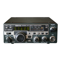
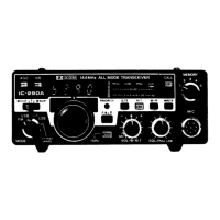
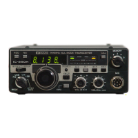
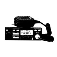
Identification of front panel controls and explanation of Mode, Tuning, VFO, and Volume.

SECTION V OPERATION

TUNING AND FREQUENCY MANAGEMENT

Instructions for tuning, preset frequencies, display modes, and VFO/Memory operations.

MEMORY CHANNEL OPERATIONS

SCANNING OPERATIONS

SSB OPERATION

SSB RECEIVING AND TRANSMITTING

How to receive and transmit SSB signals, including AGC and Noise Blanker.

CW OPERATION

CW RECEIVING AND TRANSMITTING

How to receive and transmit CW signals, including monitor function.

FM OPERATION

FM RECEIVING AND TRANSMITTING

How to receive and transmit FM signals.

SECTION VII CIRCUIT DESCRIPTION

CIRCUIT ARCHITECTURE AND RECEIVER CIRCUITS

Overview of PLL, receiver circuits, antenna switching, RF, and IF stages.

TRANSMITTER AND DETECTOR CIRCUITS

Description of transmitter, detector, BFO, AF, AGC, and Noise Blanker circuits.

LOGIC AND CPU CONTROL

SECTION VIII TROUBLE-SHOOTING

SECTION IX BLOCK DIAGRAM

Related product manuals