Do you have a question about the Icom IC-2GA and is the answer not in the manual?
Information required for ordering replacement parts from the dealer or Icom Service Center.
Important safety guidelines and precautions to follow during transceiver repair procedures.
Covers general specifications like frequency coverage, mode, memory channels, and dimensions.
Details transmitter output power, modulation system, frequency deviation, and impedance.
Outlines receiver sensitivity, spurious rejection, and audio output power.
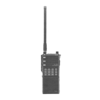
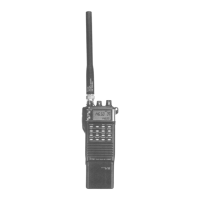
Identifies external controls and connectors on the front and side of the transceiver.
Details controls and indicators located on the top surface of the transceiver.
Explains the various segments and indicators of the transceiver's LCD display.
Shows the internal components of the main unit for IC-2GA/GAT and IC-2GE models.
Illustrates the internal components of the RF unit, including filters and oscillators.
Shows the layout and components of the speaker and DTMF units.
Illustrates the functional blocks of the transceiver and their interconnections.
Explains the function of receiver sub-circuits, including antenna switching, RF, mixers, and IF stages.
Details the microphone amplifier, drive amplifier, power amplifier, and APC circuit functions.
Describes the Phase Locked Loop system, reference oscillator, and charge pump circuits.
Explains voltage lines, the voltage regulator, and CPU power supply.
Covers S/RF meter, lamp, low voltage detector, beep, and power saver circuits.
Lists CPU pin assignments and explains keypad matrix input connections.
Lists all mechanical parts with ordering numbers and quantities.
Exploded view showing assembly of the transceiver's case and front panel.
Exploded views of the logic units, main unit, RF unit, and contact holder assembly.
Instructions on how to disconnect the RF unit from the main unit.
Details required instruments and steps for adjusting the PLL reference frequency and lock voltage.
Covers sensitivity and S/RF level indicator adjustments using test equipment.
Outlines procedures for adjusting output power, FM deviation, CTCSS, DTMF, and tone call deviation.
Diagrams showing locations for various adjustment potentiometers on the units.
Shows how the various units (Main, RF, Mic, Speaker, etc.) are interconnected.
Shows component and foil side layouts for the Logic-A and Logic-B units.
Shows the component and foil side layout for the RF unit board.
Shows component and foil side layouts for the Main unit board.
Pin diagrams for key ICs used in the transceiver.
Component layouts for VCO, PTT, Junction, Tone, and DTMF units.
Comprehensive list of electronic components for the Main Unit with part numbers.
Lists electronic components for the RF Unit, including ICs, transistors, diodes, coils, and resistors.
Lists components for the VCO Unit, including transistors, diodes, coils, and connectors.
Lists components for the Tone and DTMF units.
Lists components for the Logic Unit, including ICs, transistors, diodes, LEDs, and battery.
Provides the schematic and voltage readings for the Logic Unit.
Shows the schematic and voltage readings for the Main Unit, including various transistors and ICs.
Provides the schematic and voltage readings for the Tone Call unit (IC-2GE).
Shows the schematic and voltage readings for the VCO unit.
Provides the schematic and voltage readings for the Tone Encoder unit (IC-2GAT).
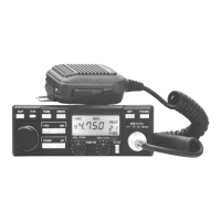
Lists charger specifications, battery pack details, and panel controls.
Explains charger operation via block diagram and circuit descriptions.
Lists mechanical parts, assembly views, and electronic components for the charger.
Provides the schematic and voltage diagram for the BC-35/BC-36 battery chargers.
Explains the function of the tone encoder/decoder and the input data table.
Shows component and foil side layouts for the UT-40 Tone Squelch Unit.
Provides the schematic and voltage readings for the UT-40 Tone Squelch Unit.
| Brand | Icom |
|---|---|
| Model | IC-2GA |
| Category | Transceiver |
| Language | English |